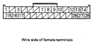
EPS Control Unit Inputs and Outputs for Connector D (28P)
 Courtesy of AMERICAN HONDA MOTOR CO., INC.
 TERMINALS REFERENCE CHART
| Terminal number |
Wire color |
Terminal sign (Terminal name) |
Description |
Signal |
| Terminals |
Conditions |
Results |
| 1 |
WHT |
CAN-H (CAN-HI) |
CAN communication circuit |
-- |
-- |
-- |
| 3 |
BLU |
NEP (Engine pulse) |
Detects tachometer signal |
3-GND |
With engine running |
Pulses |
| 7 |
BRN |
SCS (Service check signal) |
Detects service check connector signal |
7-GND |
SCS not grounded |
Battery voltage |
| 8 |
LT GRN |
VS2 (Voltage sensor 2) |
Detects torque sensor signal |
-- |
-- |
-- |
| 9 |
BRN |
PVF (Voltage fade) |
Drives the torque sensor |
-- |
-- |
-- |
| 10 |
GRN |
VS1 (Voltage sensor 1) |
Detects torque sensor signal |
-- |
-- |
-- |
| 12 |
PNK |
S1 (Signal 1) |
Detects motor angle sensor signal |
-- |
-- |
-- |
| 13 |
BLU |
R1 (Motor angle sensor 1) |
Detects motor angle sensor signal |
-- |
-- |
-- |
| 14 |
BRN |
S2 (Signal 2) |
Detects motor angle sensor signal |
-- |
-- |
-- |
| 15 |
RED |
CAN-L (CAN-LO) |
CAN communication circuit |
-- |
-- |
-- |
| 16 |
YEL GRY |
IG1 (Ignition 1) |
Power source for activating the system |
16-GND |
Ignition switch ON (II) |
Battery voltage |
| Ignition switch OFF |
0V |
| 17 |
LT BLU |
K-LINE (Data link connector) |
Communicates with HDS |
17-GND |
HDS not connected |
About 5 V |
| 26 |
BRN |
S3 (Signal 3) |
Detects motor angle sensor signal |
-- |
-- |
-- |
| 27 |
PNK |
R2 (Motor angle sensor 2) |
Detects motor angle sensor signal |
-- |
-- |
-- |
| 28 |
BLU |
S4 (Signal 4) |
Detects motor angle sensor signal |
-- |
-- |
-- |