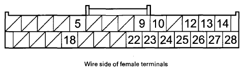
Audio-Navigation Unit Connector H (28P)
 Courtesy of AMERICAN HONDA MOTOR CO., INC.
 AUDIO-NAVIGATION UNIT CONNECTOR H (28P)
| Cavity |
Wire Color |
Terminal Name |
Description |
Voltage (about) |
Symptom |
| H5 |
YEL |
DIAG- (Diagnostic negative) |
Ground for service check signal |
0 V |
If open: The system will not go into diagnostic mode when using the SCS service connector. If short to ground: No effect on system. |
| H9 |
BLK |
NAVI COMM4 (HFL communication 4) |
Communication signal for HFL |
4.5 V DC |
Solid red HFL icon in Navi System Link. Phone icon in the Route To screen is grayed out. |
| H10 |
RED |
NAVI COMM2 (HFL communication 2) |
Communication signal for HFL |
4.5 V DC |
HFL icon in Navi System Link changes between red and green. Phone icon in the Route To screen is grayed out. |
| H12 |
WHT |
F-CAN H (F-CAN high) |
F-CAN bus communication |
Pulses 2.5- 6 V average 2.5 V (depends on F-CAN communication traffic) |
If open:
- System Link Meter shown as red.
- F-CAN System Link = NG.
- Car status IGNITION = 0.
If short: Same diagnostic conditions as when open, and also sets U0029 (F-CAN BUS OFF). |
| H13 |
GRY |
JOG SH (Interface dial Shield jog) |
Shield for terminal No. 26 |
- - |
- - |
| H14 |
GRY |
MIC SIG SH (HFL mic signal shield) |
Shield for terminals No. 27 and No. 28 |
0 V |
If open: No effect on voice control. If short to ground: No effect on voice control. |
AUDIO-NAVIGATION UNIT CONNECTOR H (28P)
| Cavity |
Wire Color |
Terminal Name |
Description |
Voltage (about) |
Symptom |
| H18 |
RED |
DIAG + (Diagnostic positive) |
Service check signal for navigation system |
5- 6V |
If open: No effect on system. If short to ground: System goes into diagnostic mode at ACC or ON mode. |
| H22 |
GRN |
NAVI COMM3 (HFL communication 3) |
Communication signal for HFL |
5 V DC |
Solid red HFL icon in Navi System Link. Phone icon in the Route To screen is grayed out. |
| H23 |
WHT |
NAVI COM Ml (HFL communication 1) |
Communication signal for HFL |
5 V DC |
HFL icon in Navi System Link changes between red and green. Phone icon in the Route To screen is grayed out. |
| H24 |
GRY |
NAVI COMM SH (shield HFL) |
Shield for terminals No. 9, No. 10, No. 22, and No. 23 |
0 V |
- - |
| H25 |
BLK |
F-CAN L (F-CAN low) |
F-CAN bus communication |
Pulses 2.5- 6 V average 2.5 V (depends on F-CAN communication traffic) |
If open:
- System Link Meter shown as red.
- F-CAN System Link = NG.
- Car status IGNITION = 0.
If short: Same diagnostic conditions as when open, and also sets U0029 (F-CAN BUS OFF). |
| H26 |
BLU |
JOG (Interface dial Jog) |
Interface dial operation signal |
0- 5 V pulses |
If open: You cannot operate navigation system. If short to ground: You cannot operate navigation system. |
| H27 |
RED |
MIC SIG-(HFL mic signal negative) |
Ground for microphone signal |
0 V |
If open: microphone signal shown as red in diagnostics: System Link and Functional Setup Mic Level. If short to ground: No effect on voice recognition. |
| H28 |
GRN |
MIC SIG + (HFL mic signal positive) |
Microphone output signal positive |
4- 5 V (TALK button pressed) |
If open: microphone signal shown as red in diagnostic screens: System Link and Functional Setup Mic Level.
If short to ground: microphone signal shown as red in diagnostic screens: System Link and Functional Setup Mic Level. |