Initialization Test
- Disconnect 6-wire connector at MCU and check for battery voltage at harness side terminal 12. If battery voltage is not present, inspect and repair voltage supply circuit.
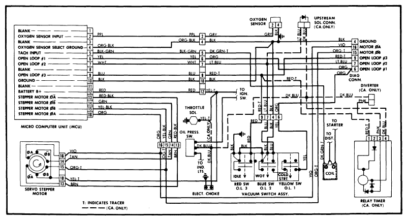 Courtesy of AMERICAN MOTORS/RENAULT CORP.
- Test harness side terminal 10 for continuity to ground. If not continuous, repair open in ground circuit 10.
- Disconnect 4-wire connector and measure resistance between harness side terminal 12 and each of harness side terminals of 4-wire connector. All 4 indications should be nearly equal and be between 50 and 95 ohms. If okay, proceed to step 6. If not okay, continue to step 4)
.
- Disconnect 5-wire stepper motor connector and measure resistance between stepper motor side terminal 18 and stepper motor housing. Resistance should be infinite.
- Measure resistance between terminal 18 and other 4 terminals of motor side connector. Resistance should be nearly equal and be between 53 and 85 ohms for all four. If steps 4)
and 5)
show stepper motor to be okay, repair wiring harness between stepper motor and MCU. If not okay, replace stepper motor.
- With ignition "ON", check for battery voltage at harness side terminal 18 (5-wire connector). If battery voltage is present, continue to step 7
). If not, repair voltage supply circuit.
- With ignition "OFF", remove stepper motor and push metering pins fully into motor. Reinstall motor and carefully reconnect 5-wire connector. Observe pins while ignition is turned to "ON" position. If pins move, replace stepper motor. If pins do not move, replace MCU.