Removal & Installation
- Remove rear cover on wheel arch (left side).
- Before removing ABS/ASC+T/DSC Control module, read out fault memory and, if necessary, print out trouble code.
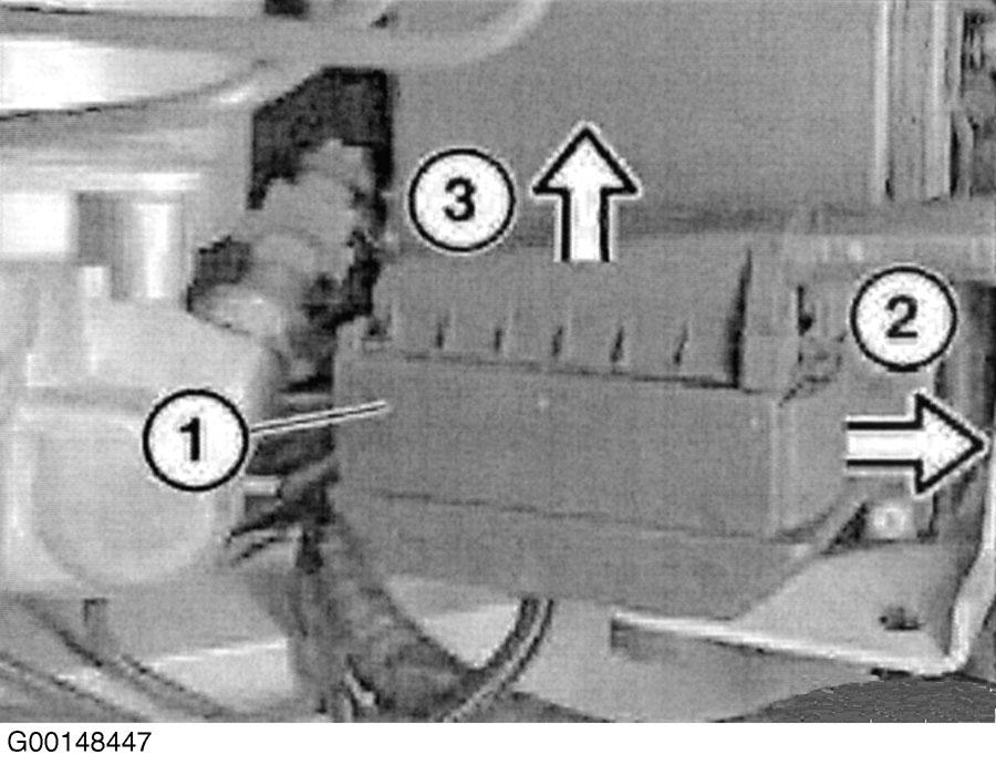
- Unfasten plug connection lock (1) in direction (2). Detach plug connection (1) in direction (3) vertically towards top. See Fig 1
.
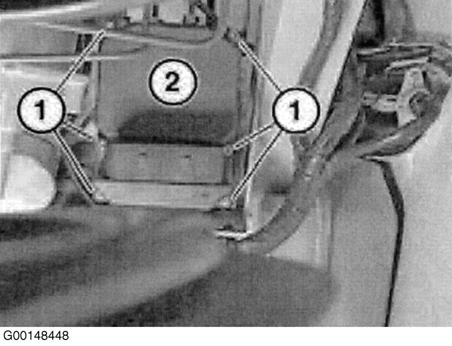
- Release screws (1) and detach control module (2) from hydraulic unit. See Fig 2
.
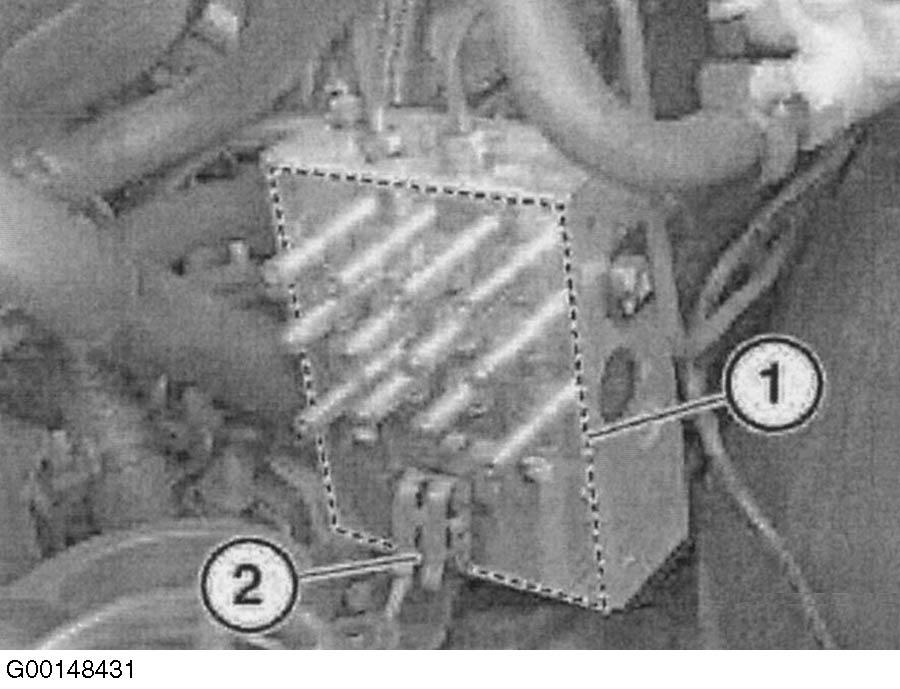
- Before installation, check sealing surface (1) between control module and hydraulic unit for damage. Clean sealing surface. Check contact lugs (2) for corrosion or damage and repair as necessary. See Fig 3
.
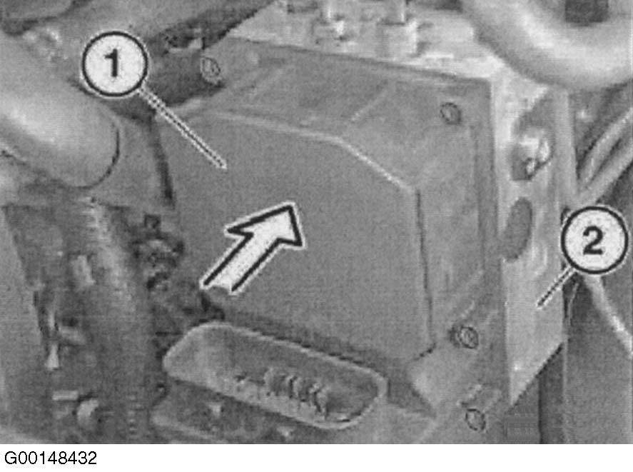
- Carefully push control module (1) onto hydraulic unit (2). Ensure solenoid coils are not tilted. See Fig 4
.
- Housing edge of control module (1) must slide over extension on hydraulic unit (2). See Fig 5
.
- Install (do not tighten down) NEW screws (1 and 2) uniformly until control module rests evenly on hydraulic unit. Install new screws (3-6), do not tighten down. Tighten down screws (1-6) in specified sequence. See Fig 6
.
- Tighten screws to specification. See TORQUE SPECIFICATIONS
.
- Position plug connection vertically on control module so as to avoid damaging pins. Slide connector lock into place.
- Using Diagnosis and Information System (DIS) tester, re-code new control module. If vehicle is equipped with Dynamic Stability Control (DSC), perform steering angle sensor adjustment under DIS tester SERVICE FUNCTIONS menu. Using DIS tester, perform end-of-belt test.
 Courtesy of BMW OF NORTH AMERICA, INC.
 Courtesy of BMW OF NORTH AMERICA, INC.
 Courtesy of BMW OF NORTH AMERICA, INC.
 Courtesy of BMW OF NORTH AMERICA, INC.
 Courtesy of BMW OF NORTH AMERICA, INC.
 Courtesy of BMW OF NORTH AMERICA, INC.