Measuring Procedure
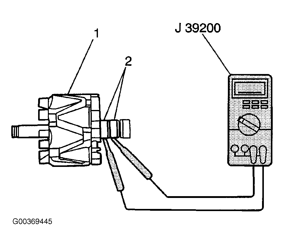
- Measure the resistance between the rotor slip rings using J 39200. If the resistance is greater than 2.5-2.9 ohms, replace the rotor. See Fig 1
.
- Measure the resistance between the rotor slip rings and the rotor using the J 39200. If the resistance is less than 5 ohms, replace the rotor. Inspect the rotor slip rings for roughness or scoring. If the slip rings are rough or scored, replace the rotor.
- Measure the resistance between all stator leads using J 39200. If the resistance is greater than 5 ohms for any measurement, replace the stator.
- Measure the resistance between all stator leads and the stator core using J 39200. If the resistance is less than 5 ohms, replace the stator.
- Measure the length of each brush using J 26900-5. If the brush length is less than the minimum, replace the brush. See GENERATOR SPECIFICATIONS
.
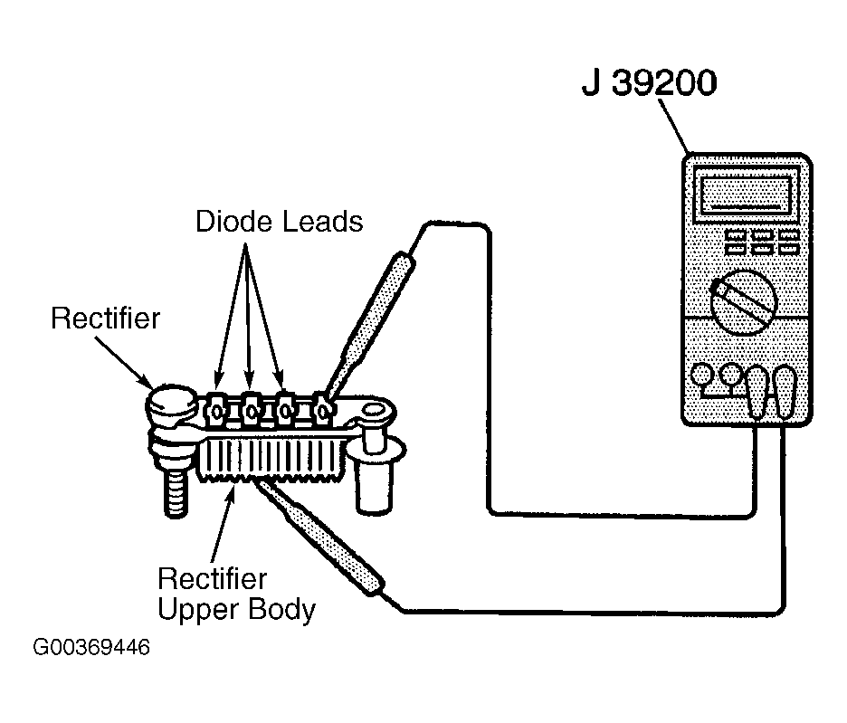
- Measure the resistance between the rectifier upper body and each diode lead using J 39200. See Fig 2
. Reverse the probes and measure the resistance again. The resistance should be less than 5 ohms in one measurement and greater than 5 ohms in the other measurement. If not, replace the rectifier.
- Measure the resistance between the rectifier lower body and each diode lead using the J 39200. Reverse the probes and measure the resistance again. The resistance should be less than 5 ohms in one measurement and greater than 5 ohms in the other measurement. If not, replace the rectifier.
- Measure the resistance between both leads of each rectifier diode trio using the J 39200. Reverse the probes and measure the resistance again. The resistance should be less than 5 ohms in one measurement and greater than 5 ohms in the other measurement. If not, replace the rectifier.
- Measure the condenser capacity using a digital capacitor meter. If the condenser capacity is not 0.5 microfarads, replace the rectifier.
 Courtesy of GENERAL MOTORS CORP.
 Courtesy of GENERAL MOTORS CORP.