Installation Procedure
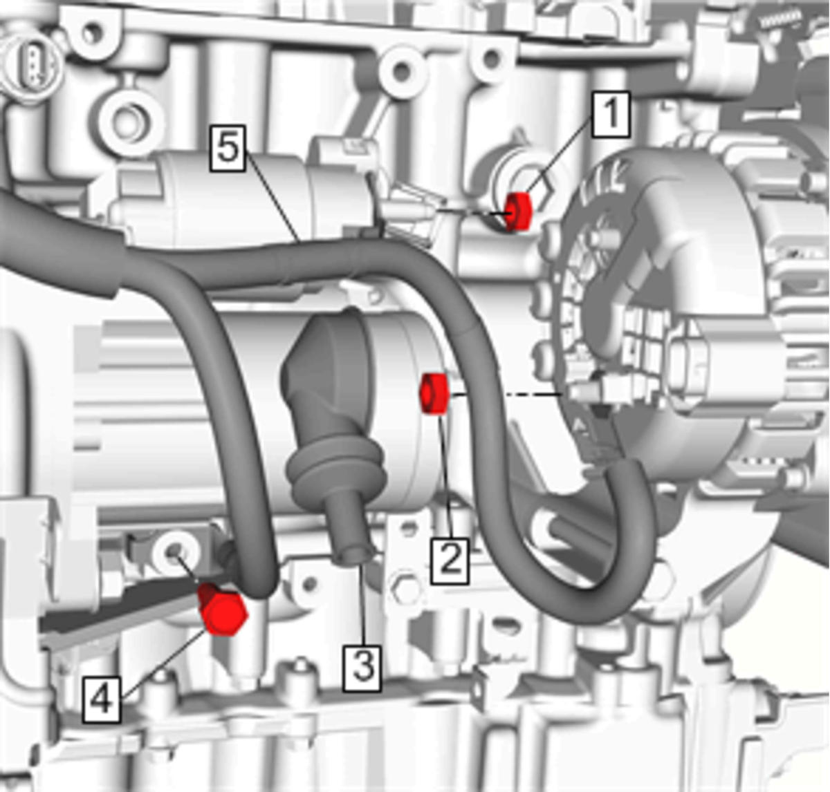
- Install the battery positive cable (5) to the generator B (+) stud and tighten the generator B (+) nut (2) to 14 N.m (10 lb ft).
 Courtesy of GENERAL MOTORS COMPANY
- Install the protective cover (3).
- Install the battery positive cable nut (1) and tighten to 14 N.m (10 lb ft).
- Install the battery positive cable ground bolt (4) and tighten to 22 N.m (16 lb ft).
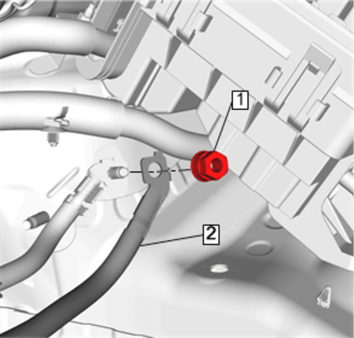
- Install the battery positive cable (2) to the frame stud ground and tighten the battery negative and positive ground nut (1) to 22 N.m (16 lb ft).
 Courtesy of GENERAL MOTORS COMPANY
- Install the battery. Refer to Battery Replacement .
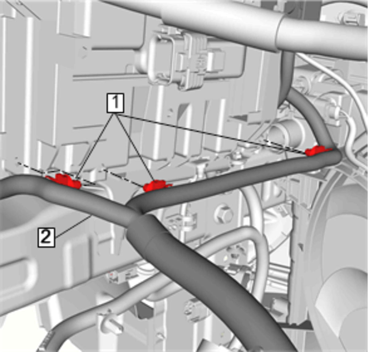
- Install the battery positive cable retainers (1) and the battery positive cable to the battery tray.
 Courtesy of GENERAL MOTORS COMPANY
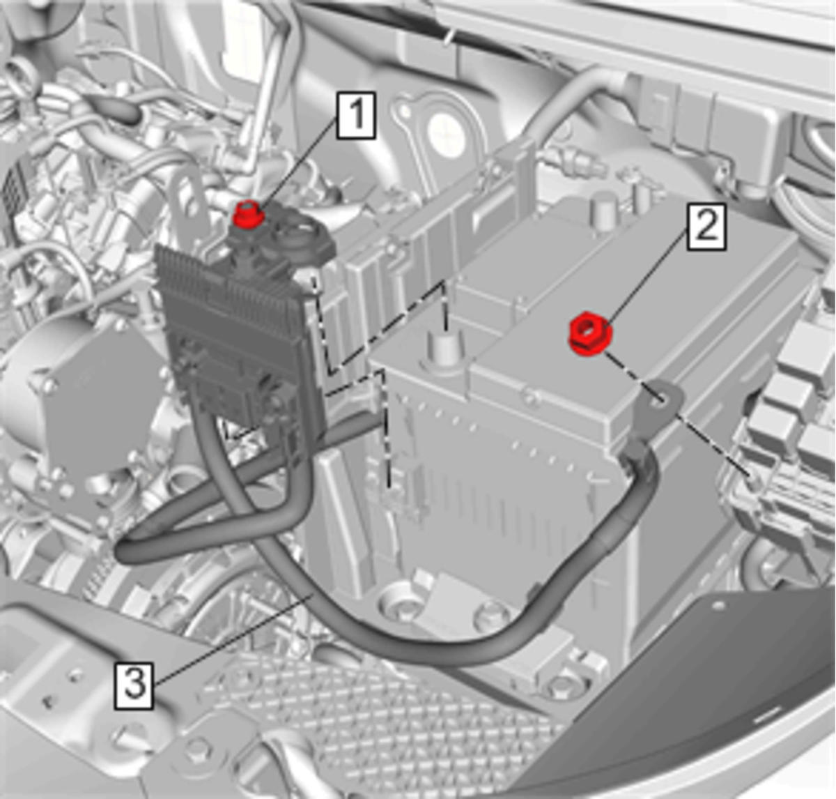
- Install the battery positive cable (3) to the battery and the engine wiring harness junction block.
 Courtesy of GENERAL MOTORS COMPANY
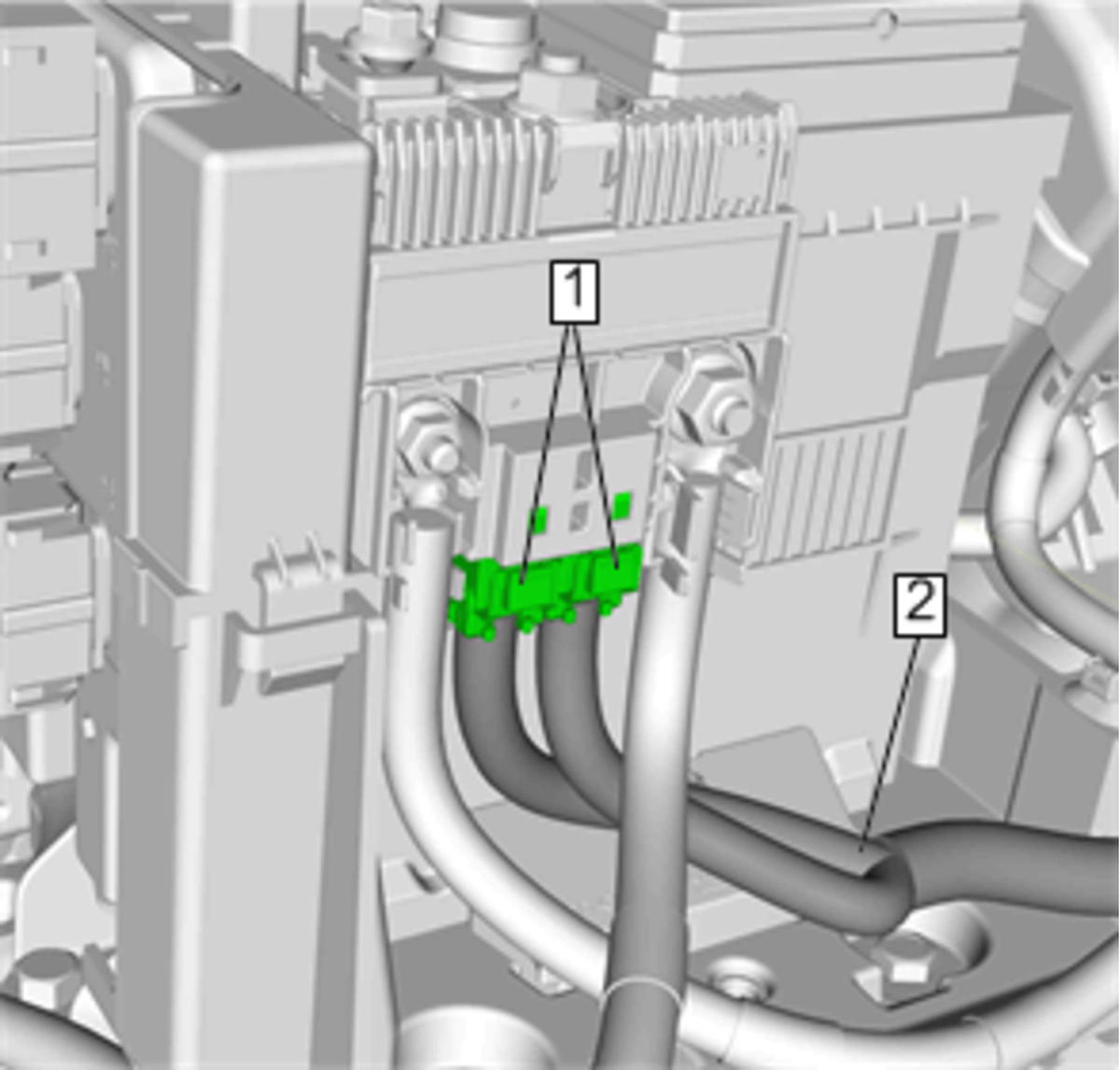
- Install the battery positive cable junction block post nut (1) and tighten to 6 N.m (53 lb in).
- Install the engine wiring harness junction block nut (2) and tighten to 22 N.m (16 lb ft).
- Install the body wiring harness (2) to the battery positive cable junction block and connect the body wiring harness connectors (1).
 Courtesy of GENERAL MOTORS COMPANY
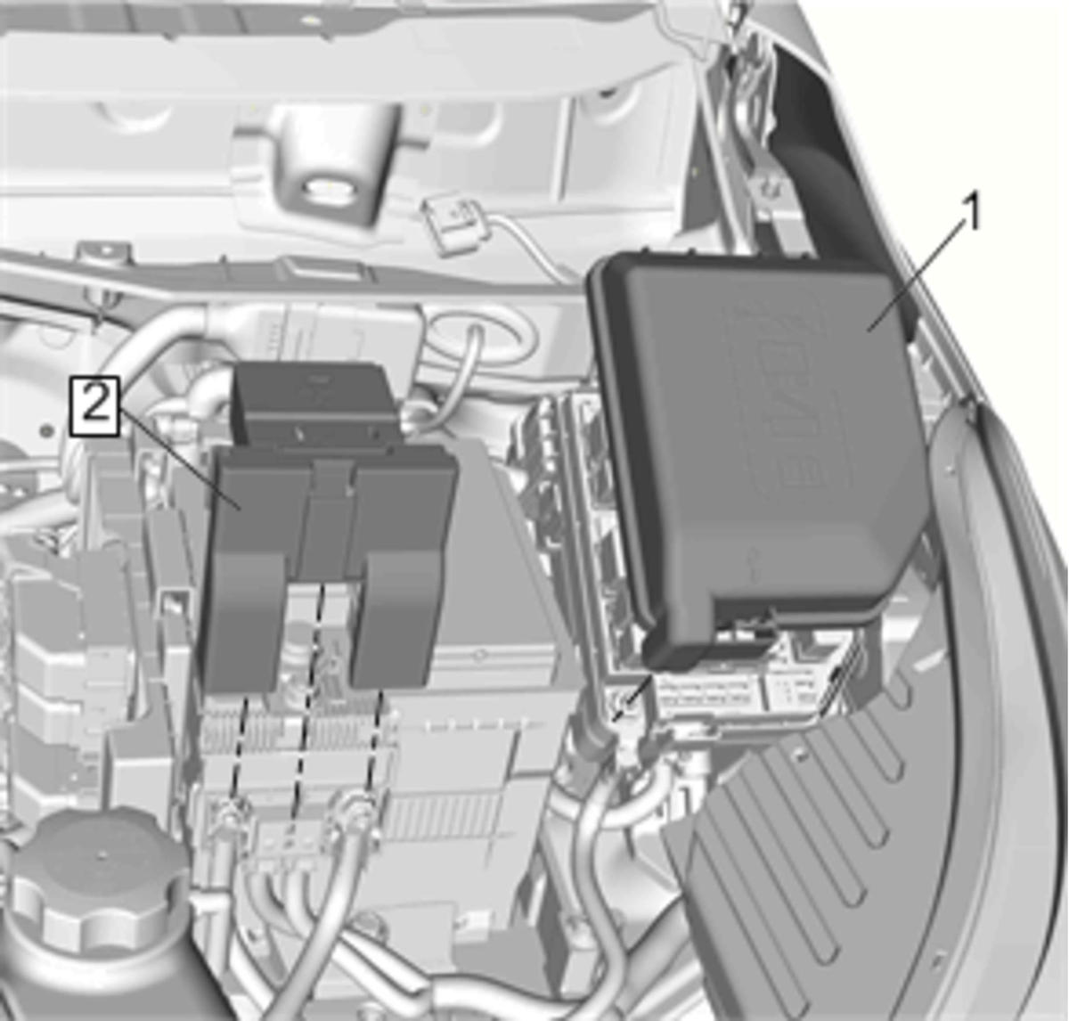
- Install the battery positive cable terminal cover (2).
 Courtesy of GENERAL MOTORS COMPANY
- Install the engine wiring harness junction block cover (1).
- Install the engine control module (S53) to the battery tray. Refer to Engine Control Module Replacement
- Connect the battery negative cable. Refer to Battery Negative Cable Disconnection and Connection .