October 30: LEMON manuals on a temporary server, it is slow and having issues, download the manuals you need! Later in November we will switch back to the fast server.
System Test
- With ignition off, disconnect Transmission Control Module (TCM). See Fig 1
. Disconnect 2-pin and 3-pin connectors at Speed Proportional Steering Module (SPSM). See Fig 2
. Inspect connectors and clean or repair if necessary.
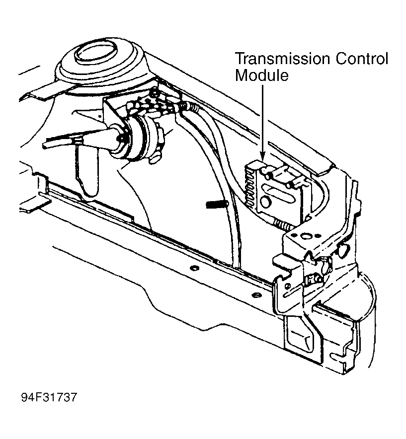 Courtesy of CHRYSLER CORP.
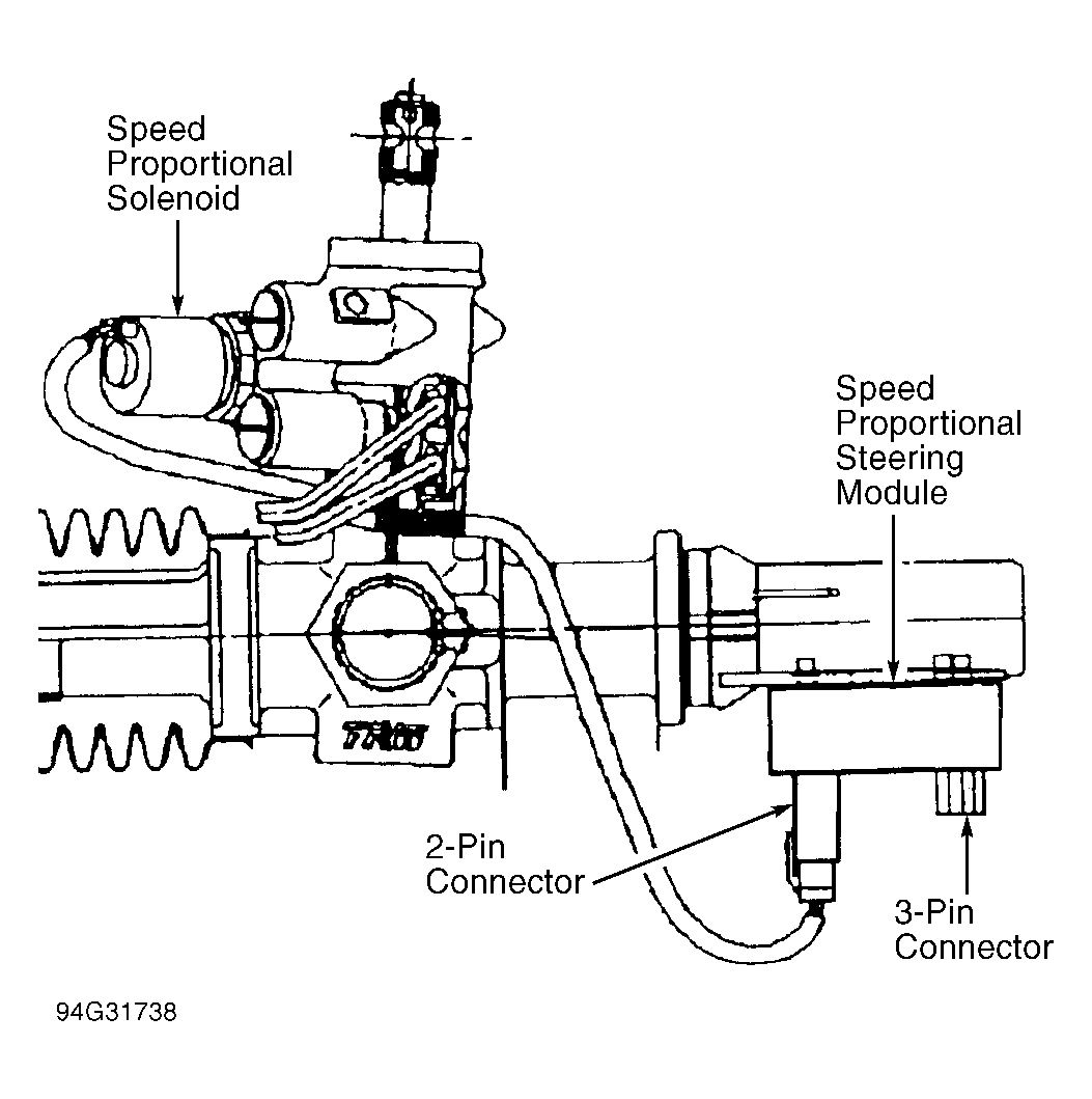 Courtesy of CHRYSLER CORP.
- Using an ohmmeter, measure resistance on VSS Signal Circuit (pin No. 3). See Fig 3
. If resistance is greater than 5 ohms, repair open in vehicle speed sensor circuit and perform TEST VER-1
. If resistance is less than 5 ohms, go to next step.
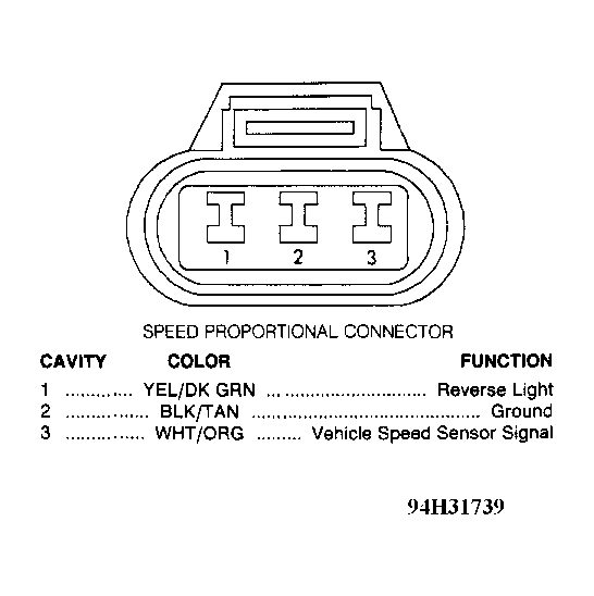 Courtesy of CHRYSLER CORP.
- Using an ohmmeter, measure resistance on VSS signal circuit (pin No. 58). See Fig 4
. If resistance is less than 5 ohms, repair VSS signal circuit for short to ground and perform TEST VER-1
. If resistance is greater than 5 ohms, go to next step
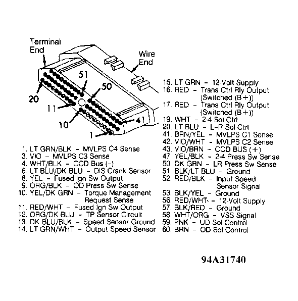 Courtesy of CHRYSLER CORP.
- Using an ohmmeter, probe ground circuit. See Fig 4
. If resistance is greater than 5 ohms, repair open ground circuit and perform TEST VER-1
. If resistance is less than 5 ohms, go to next step.
- With ignition on, use a voltmeter to probe the fused ignition switch output circuit (pins No. 8 and 11). See Fig 4
. If the voltage is less than 9 volts, repair open fused ignition switch output circuit and perform TEST VER-1
. If voltage is greater than 9 volts, go to next step.
- Using an ohmmeter, measure across solenoid control valve circuit 2 pin connector. See Fig 2
. If resistance is 5-7 ohms, replace speed proportional steering module and perform TEST VER-1
. If resistance is not 5-7 ohms, replace solenoid control valve and pigtail. Perform TEST VER-1
.