September 30: LEMON manuals is back up on a temporary server! Slowness is possible
Colt Vista
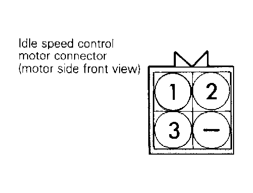
- Disconnect MPS connector. See Fig 1
. Connect ohmmeter lead to ground. Connect other ohmmeter lead to terminal No. 3 of sensor connector. If continuity is not present, repair wiring harness as necessary. If continuity is present, go to next step.
- Connect ohmmeter leads to terminals No. 1 and 3. See Fig 1
. Resistance for all models should be 4000-6000 ohms. If resistance is not within specified range, replace MPS.
 Courtesy of MITSUBISHI MOTOR SALES OF AMERICA.
CAUTION:
DO NOT
apply more than 6 volts to ISC motor.
- Operate ISC motor by connecting a 6-volt source directly to appropriate terminals of ISC motor connector. For ISC motor operation test procedures, see IDLE SPEED CONTROL (ISC) MOTOR OPERATION TEST
under IDLE CONTROL SYSTEM.
- While operating ISC motor, measure resistance between MPS connector terminals No. 1 and 2. Observe ohmmeter during ISC motor operation. If MPS resistance does not vary within a 4000-6000 ohm range or if resistance does not change smoothly, replace MPS (vehicles equipped with separate MPS) or ISC motor assembly (vehicles equipped with MPS incorporated in ISC).