Aw60T Automatic Transaxle (Service Information): Disassembly: Disassembly
 Courtesy of CHRYSLER GROUP, LLC
- Remove the transmission control module. Refer to MODULE, TRANSMISSION CONTROL [EAJ], REMOVAL
or MODULE, TRANSMISSION CONTROL [EAB], REMOVAL
.
- Remove the valve body assembly. Refer to VALVE BODY, REMOVAL .
- Remove the external oil cooler Refer to COOLER, TRANSMISSION OIL, REMOVAL
.
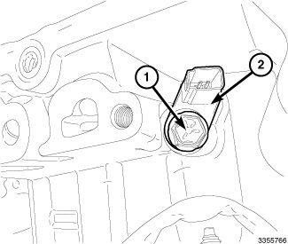
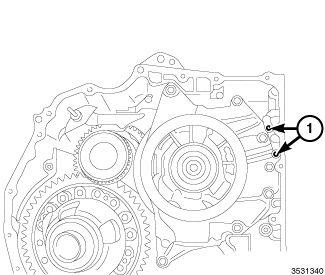
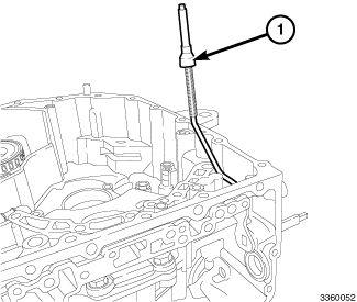
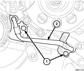
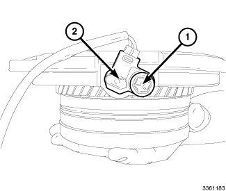
- Remove the input speed sensor bolt (1) and remove the input speed sensor (2) from the case.
 Courtesy of CHRYSLER GROUP, LLC
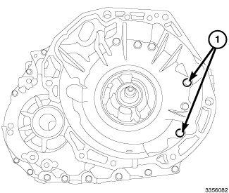
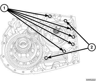
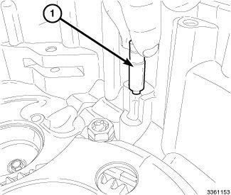
- Remove the transaxle case bolts. Note that the longer bolts are in positions (1).
 Courtesy of CHRYSLER GROUP, LLC
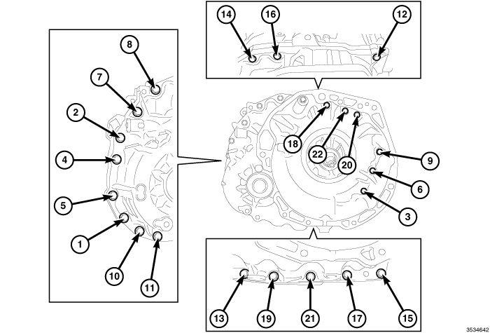
- Remove the transaxle case bolts using this sequence.
 Courtesy of CHRYSLER GROUP, LLC
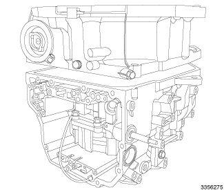
- Separate the case halves.
 Courtesy of CHRYSLER GROUP, LLC
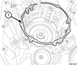
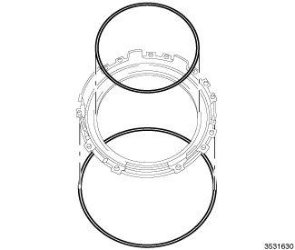
- Remove the two transaxle case gaskets (1).
 Courtesy of CHRYSLER GROUP, LLC
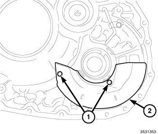
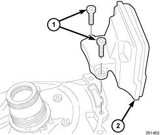
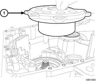
- Remove the oil reservoir lock plate bolts (1) and remove the lock plate (2).
 Courtesy of CHRYSLER GROUP, LLC
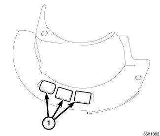
- Remove the magnets (1) from the oil reservoir lock plate.
 Courtesy of CHRYSLER GROUP, LLC
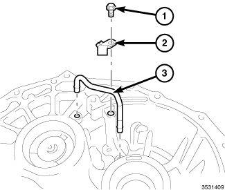
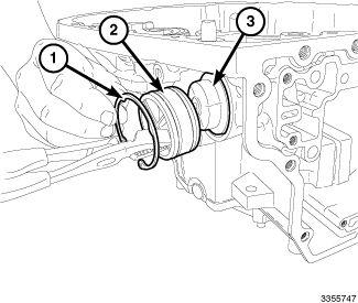
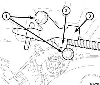
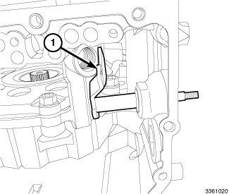
- Remove the bolt (1) and retention tab (2). Using a screw driver or the equivalent, carefully remove the tube (3).
 Courtesy of CHRYSLER GROUP, LLC
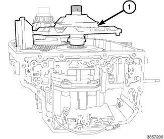
- Remove the oil pump bolts (1). The longer bolts are in position (2)
 Courtesy of CHRYSLER GROUP, LLC
- Remove the oil pump.
 Courtesy of CHRYSLER GROUP, LLC
- Remove the oil strainer bolts (1) and the oil strainer (2).
 Courtesy of CHRYSLER GROUP, LLC
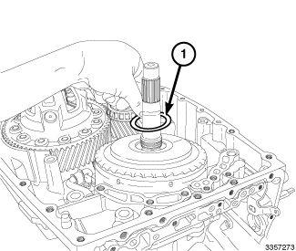
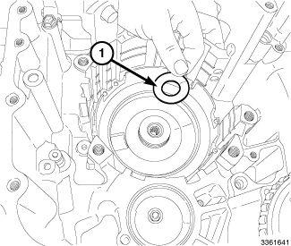
- Remove the nylon thrust washer (1).
 Courtesy of CHRYSLER GROUP, LLC
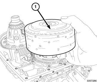
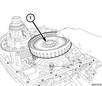
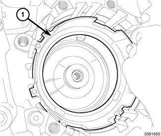
- Remove the B1 brake / C3 clutch assembly (1).
 Courtesy of CHRYSLER GROUP, LLC
- Remove the front planetary carrier and input shaft annulus gear assembly.
 Courtesy of CHRYSLER GROUP, LLC
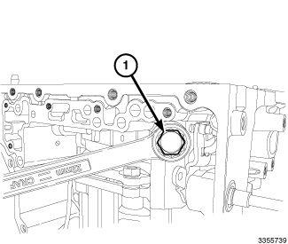
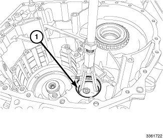
- Remove the B1 band bolt (1).
 Courtesy of CHRYSLER GROUP, LLC
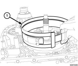
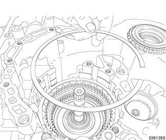
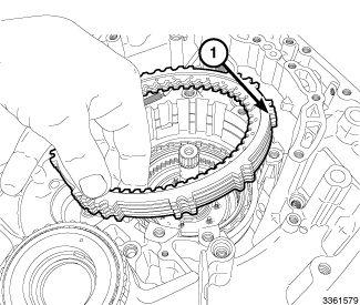
- Remove the B1 brake band (1).
 Courtesy of CHRYSLER GROUP, LLC
- Remove the B1 brake band servo, spring and piston rod. Discard the O-rings.
 Courtesy of CHRYSLER GROUP, LLC
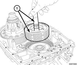
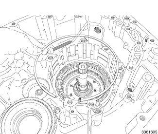
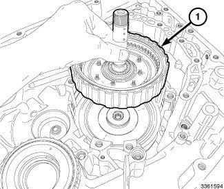
- Remove the C1 clutch assembly (1).
 Courtesy of CHRYSLER GROUP, LLC
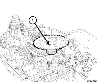
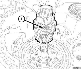
- Remove the sun gear input drum (1).
 Courtesy of CHRYSLER GROUP, LLC
- Remove the thrust washers and bearings.
 Courtesy of CHRYSLER GROUP, LLC
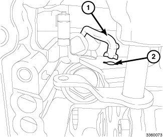
- Remove the parking pawl actuator bracket bolts (1). Disconnect the actuator rod (2) from the bracket (3).
 Courtesy of CHRYSLER GROUP, LLC
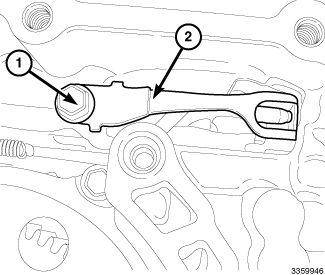
- Remove the manual shift shaft detent bolt (1), remove the detent (2).
 Courtesy of CHRYSLER GROUP, LLC
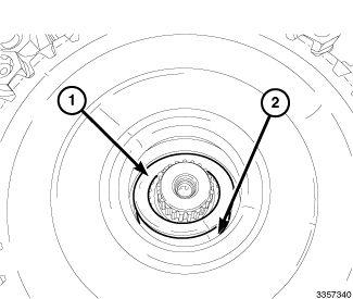
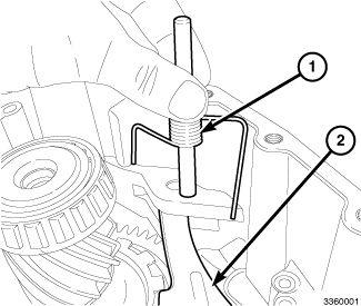
- Remove the parking pawl spring and pivot assembly (1), remove the parking pawl (2).
 Courtesy of CHRYSLER GROUP, LLC
- Rotate the actuator rod (1) up and turn the manual shift lever (2) so the rod key slot and tabs line up, disconnect.
 Courtesy of CHRYSLER GROUP, LLC
- Remove the actuator rod (1).
 Courtesy of CHRYSLER GROUP, LLC
- Remove the plunger from the case (1).
 Courtesy of CHRYSLER GROUP, LLC
- Remove the manual lever (1).
- Remove the manual lever seal.
 Courtesy of CHRYSLER GROUP, LLC
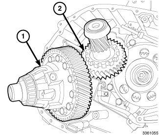
- Remove the counter gear shaft (2) and the differential (1).
 Courtesy of CHRYSLER GROUP, LLC
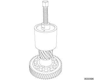
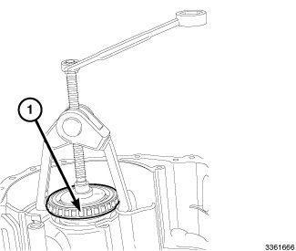
- Using (special tool #6055, Thrust Button) and (special tool #5048, Puller, Bearing) remove the right side inner bearing.
 Courtesy of CHRYSLER GROUP, LLC
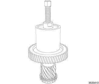
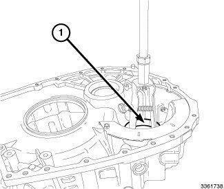
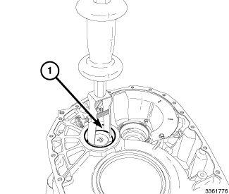
- Remove the left side inner bearing.
 Courtesy of CHRYSLER GROUP, LLC
- Remove the fluid transfer pipe bolts (1) and remove the transfer pipe (2).
 Courtesy of CHRYSLER GROUP, LLC
- Remove the counter drive gear assembly bolts.
- Remove the counter drive gear assembly (1).
 Courtesy of CHRYSLER GROUP, LLC
- Remove the output speed sensor bolt (1) and speed sensor (2).
 Courtesy of CHRYSLER GROUP, LLC
- Remove the snap ring (1).
 Courtesy of CHRYSLER GROUP, LLC
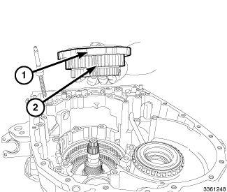
- Remove the large and small rear planetary gears (1).
 Courtesy of CHRYSLER GROUP, LLC
- Remove the rear planetary carrier and one way clutch as a unit (1 and 2).
 Courtesy of CHRYSLER GROUP, LLC
- Remove the thrust needle roller bearing and the 2 bearing races.
 Courtesy of CHRYSLER GROUP, LLC
- Remove the snap ring (1).
 Courtesy of CHRYSLER GROUP, LLC
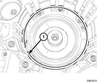
- Remove B2 disc pack (1).
 Courtesy of CHRYSLER GROUP, LLC
- Remove snap ring.
 Courtesy of CHRYSLER GROUP, LLC
- Remove C2 clutch assembly (1).
 Courtesy of CHRYSLER GROUP, LLC
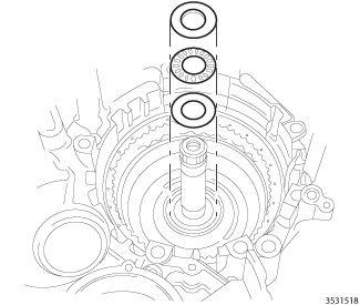
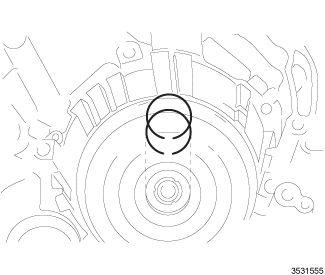
- Remove the two oil seal rings from the case.
 Courtesy of CHRYSLER GROUP, LLC
- Remove the snap ring.
 Courtesy of CHRYSLER GROUP, LLC
- Remove the 1st gear and reverse brake return spring from the case (1).
 Courtesy of CHRYSLER GROUP, LLC
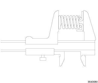
- Inspect the return spring. Measure the free length of each of the piston return springs. If the free length of any spring is less than 23 mm (0.91 in) replace the spring.
 Courtesy of CHRYSLER GROUP, LLC
- Remove the thrust washer (1).
 Courtesy of CHRYSLER GROUP, LLC
- Remove the 1st gear and reverse brake piston (1).
 Courtesy of CHRYSLER GROUP, LLC
- Remove the O-rings from the 1st gear and reverse brake piston.
- Remove the needle bearing from the case.
 Courtesy of CHRYSLER GROUP, LLC
- Using (special tool #9664, Remover, Bearing Cup) and (special tool #C-637, Slide Hammer, Universal), remove the case side transfer shaft bearing race.
 Courtesy of CHRYSLER GROUP, LLC
- Using (special tool #C-3894-A, Puller, Tie Rod) and (special tool #6454, Remover, Bearing Cup) remove the tapered differential side bearing from the case. Do not damage the shim.
 Courtesy of CHRYSLER GROUP, LLC
- Using (special tool #9664, Remover, Bearing Cup) and (special tool #C-637, Slide Hammer, Universal), remove the bell housing side differential bearing race.
 Courtesy of CHRYSLER GROUP, LLC
- Using (special tool #9664, Remover, Bearing Cup) and (special tool #C-637, Slide Hammer, Universal), remove the bell housing side transfer shaft bearing race.