September 30: LEMON manuals is back up on a temporary server! Slowness is possible
Mini ISO Relay
- Remove mini ISO relay. Measure resistance between appropriate relay terminals. See MINI ISO RELAY RESISTANCE SPECIFICATIONS
table. See Fig 1
. If resistance is as specified, go to next step. If resistance is not as specified, replace relay.
MINI ISO RELAY RESISTANCE SPECIFICATIONS
| Between Terminals No. |
Resistance |
| 85 & 86 |
50-100 Ohms |
| 30 & 87a |
5 Ohms Or Less |
| 30 & 87 |
Greater Than 10 k/Ohms |
| 30 & 86 |
Greater Than 10 k/Ohms |
| 86 & 87a |
Greater Than 10 k/Ohms |
| 86 & 87 |
Greater Than 10 k/Ohms |
- Using a fused jumper wire, connect positive battery voltage to terminal No. 85. Using another jumper wire, ground terminal No. 86. Resistance should now be 5 ohms or less between terminals No. 30 and 87 and greater than 10 k/ohms between terminals 30 and 87a. If resistance is as specified, relay is okay at this time. If resistance is not as specified, replace relay.
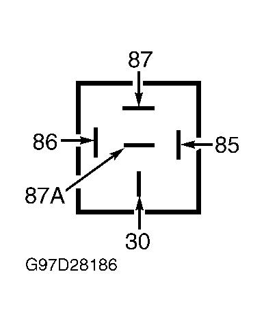 Courtesy of FORD MOTOR CO.