Pinpoint Test B: No Communication With The 4WD Control Module
- B1 CHECK CIRCUITS 1002 (BK/PK), 640 (RD/YE) AND 33a (WH/PK) FOR VOLTAGE
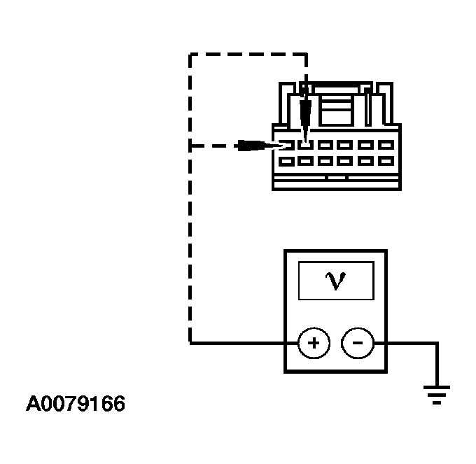
- Key in OFF position.
- Disconnect: 4WD Control Module C281a.
- Disconnect: 4WD Control Module C281b.
- Key in ON position.
- Measure the voltage between 4WD control module C281a, pin 5, circuit 640 (RD/YE) and ground; 4WD control module C281a, pin 6, circuit 1002 (BK/PK) and ground; 4WD control module C281b, pin 8, circuit 33a (WH/PK) (pick-up only) and ground.
 Courtesy of FORD MOTOR CO.
 Courtesy of FORD MOTOR CO.
- Are the voltages greater than 10 volts?
- Yes
: GO to B2.
- No
: REPAIR the circuits as necessary. TEST the system for normal operation.
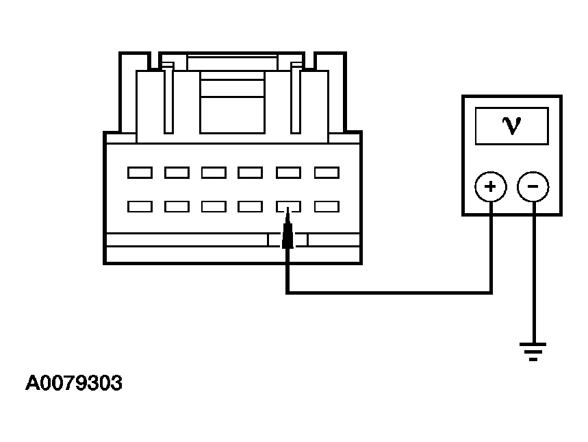
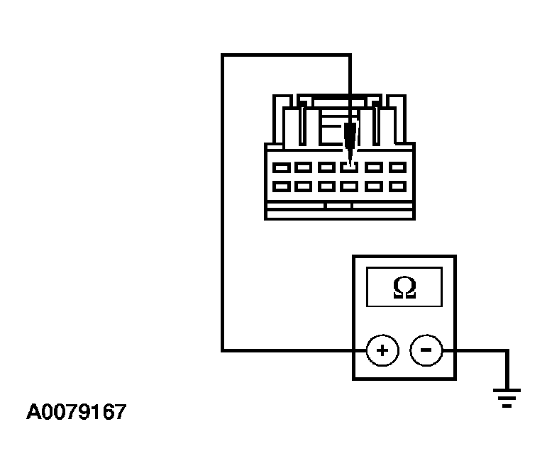
- B2 CHECK CIRCUIT 57 (BK) FOR OPEN
- Measure the resistance between 4WD control module C281a pin 3, circuit 57 (BK), harness side and ground.
 Courtesy of FORD MOTOR CO.
- Is the resistance less than 5 ohms?
- Yes
: CHECK the module communication network. refer to MODULE COMMUNICATIONS NETWORK
.
- No
: REPAIR the circuit. TEST the system for normal operation.