Pinpoint Test P: All HVAC Functions Inoperative
- P1 CHECK THE HVAC MODULE VOLTAGE SUPPLY CIRCUITS FOR AN OPEN
- Ignition OFF.
- Disconnect: HVAC Module C228A.
- Ignition ON.
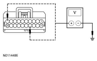
- With the engine running, measure the voltage between ground and:
- HVAC module C228A-10, circuit SBP07 (WH/RD), harness side.
- HVAC module C228A-14, circuit CBP21 (BU/GY), harness side.
 Courtesy of FORD MOTOR CO.
- Are the voltages greater than 10 volts?
- Yes
: GO to P2.
- No
: REPAIR circuit SBP07 (WH/RD) or CBP21 (BU/GY) for high resistance. CLEAR all CMDTCs. REPEAT the self-test.
- P2 CHECK THE HVAC MODULE GROUND CIRCUIT FOR AN OPEN
- Ignition OFF.
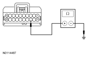
- Measure the resistance between ground and HVAC module C228A-13, circuit GD115 (BK/GY), harness side.
 Courtesy of FORD MOTOR CO.
- Is the resistance less than 5 ohms?
- Yes
: GO to P3.
- No
: REPAIR circuit GD115 (BK/GY) for high resistance. CLEAR all CMDTCs. REPEAT the self-test. TEST the system for normal operation.
- P3 CHECK THE HVAC MODULE CONNECTION
- Disconnect all the HVAC module connectors.
- Inspect the HVAC module connectors for:
- corrosion.
- pushed-out terminals.
- damaged terminals.
- Connect and correctly seat all the HVAC module connectors.
- Operate the system and verify the concern is still present.
- Is the concern still present?
- Yes
: INSTALL a new HVAC module. REFER to
CLIMATE CONTROL
. TEST the system for normal operation.
- No
: The system is operating correctly at this time. The concern may have been caused by a loose or corroded connector. TEST the system for normal operation.