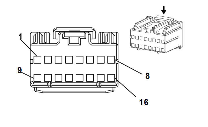
Vehicle Communications Interface Module (VCIM) X1 (UE1)
 Courtesy of Courtesy of
|
Connector Part Information
- Harness Type: Body
- OEM Connector: 15431362
- Service Connector: 15306351
- Description: 16-Way F Micro-Pack 100A Series (NA)
|
Terminal Part Information
- Terminated Lead: Pins: 1-3, 6, 10-12: 13575546
- Terminated Lead: Pins: 7, 15: 13575548
- Release Tool: J-38125-559
- Diagnostic Test Probe: J-35616-16 (L-GN)
- Terminal/Tray: 15445905/23
- Core/Insulation Crimp: Pins 1-3, 6, 10-12 - J/J
- Core/Insulation Crimp: Pins 7, 15 - K/K
|
Vehicle Communications Interface Module (VCIM) X1 (UE1)
| Pin |
Wire |
Circuit |
Function |
| 1 |
0.35 D-GN |
5060 |
Low Speed GMLAN Serial Data |
| 2 |
0.35 BN/WH |
2517 |
Keypad Red LED Signal |
| 3 |
0.35 YE/BK |
2516 |
Keypad Green LED Signal |
| 4-5 |
- |
- |
Not Used |
| 6 |
0.35 L-GN/BK |
2515 |
Keypad Voltage |
| 7 |
0.8 BK |
650 |
Ground |
| 8-9 |
- |
- |
Not Used |
| 10 |
0.35 TN/BK |
2500 |
High Speed GMLAN Serial Data Bus+ |
| 11 |
0.35 D-GN/WH |
2514 |
Keypad Signal |
| 12 |
0.35 TN |
2501 |
High Speed GMLAN Serial Data Bus- |
| 13-14 |
- |
- |
Not Used |
| 15 |
0.8 RD/WH |
4640 |
Battery Positive Voltage |
| 16 |
- |
- |
Not Used |