Park Pin Switch Replacement
- Remove the shift lever assembly (see SHIFT LEVER REMOVAL
).
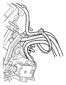
- Remove the tape from the harness.
- Remove the harness wire tie.
 Courtesy of AMERICAN HONDA MOTOR CO., INC.
- Remove the A/T gear position indicator panel, and move it up.
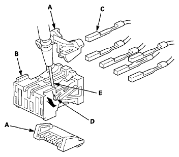
- Pry the lock covers (A) of the D3 switch/park pin switch/A/T gear position indicator panel light harness connector (B), and remove the covers.
 Courtesy of AMERICAN HONDA MOTOR CO., INC.
- Remove the terminal (C) from the connector by pushing the lock tab (D) in the connector using a thin-bladed screwdriver (E). Remove all six terminals, and replace the connector.
- Remove the park pin switch (A).
 Courtesy of AMERICAN HONDA MOTOR CO., INC.
- Install a new park pin switch, and install the A/T gear position indicator panel.
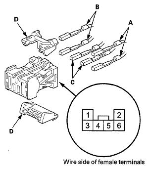
- Install the D3 switch harness terminals (WHT) (A) in the No. 1 and No. 3 cavities. Either terminal can go in either cavity.
 Courtesy of AMERICAN HONDA MOTOR CO., INC.
- Install the park pin switch harness terminals (GRN) (B) in the No. 2 and No. 6 cavities. Either terminal can go in either cavity.
- Install the A/T gear position indicator panel light harness terminals (RED/BLK) (C) in the No. 4 and No. 5 cavities. Either terminal can go in either cavity.
- Make sure that all six terminals lock securely, then install the lock covers (D) securely.
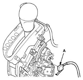
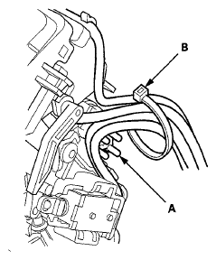
- Route the harnesses along the harness guide (A), and tie the harnesses and guide with a new wire tie (B).
 Courtesy of AMERICAN HONDA MOTOR CO., INC.
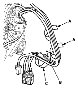
- Tie the harnesses together into bundles with new tape (A) in two places.
 Courtesy of AMERICAN HONDA MOTOR CO., INC.
- Tie the harnesses and the harness clamp (B) together into a bundle with tape (C) as shown.
- Install the shift lever assembly (see SHIFT LEVER INSTALLATION
).