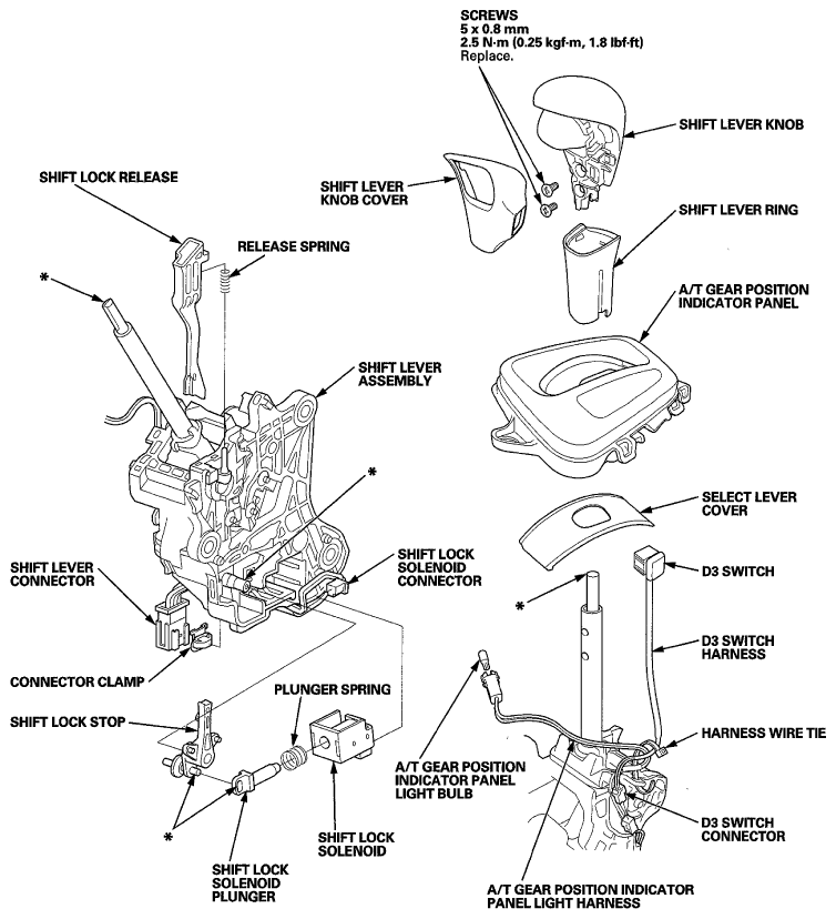
Exploded View
 Courtesy of AMERICAN HONDA MOTOR CO., INC.
- Remove the shift lever assembly (see SHIFT LEVER REMOVAL
).
- Remove the shift lever knob (see SHIFT LEVER KNOB AND SHIFT LEVER KNOB COVER REPLACEMENT
).
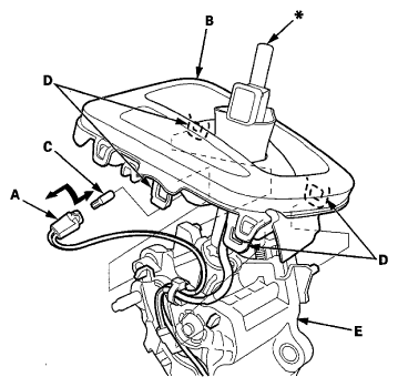
- Remove the A/T gear position indicator panel light socket (A) from the indicator panel (B), then remove the blub (C) from the socket.
 Courtesy of AMERICAN HONDA MOTOR CO., INC.
- Remove the A/T gear position indicator panel assembly by expanding the four lock tabs (D) from the shift lever assembly (E).
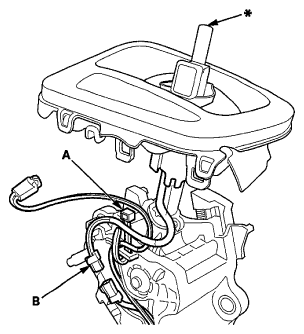
- Remove the harness wire tie (A) and disconnect the D3 switch connector (B).
 Courtesy of AMERICAN HONDA MOTOR CO., INC.
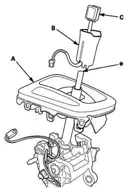
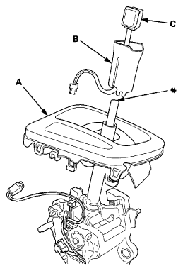
- Remove the A/T gear position indicator panel assembly (A), the shift lever ring (B), and the D3 switch (C) from the shift lever assembly.
 Courtesy of AMERICAN HONDA MOTOR CO., INC.
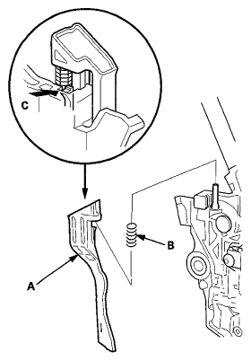
- Remove the shift lock release (A) and the release spring (B) by pressing the lock tab (C).
 Courtesy of AMERICAN HONDA MOTOR CO., INC.
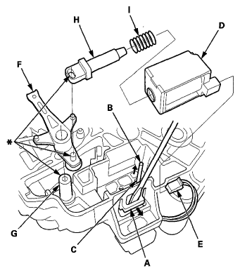
- While releasing the lock tab (A) using a screwdriver, insert a pin (B) into the guide hole (C) and push the shift lock solenoid (D) out.
 Courtesy of AMERICAN HONDA MOTOR CO., INC.
- Disconnect the shift lock solenoid connector (E).
- Remove the shift lock stop/stop cushion (F).
- Replace the shift lever/shift cable bracket assembly.
- Install the shift lock stop/stop cushion over the mounting pin (G) of the shift lever assembly.
- Connect the shift lock solenoid connector.
- Install the shift lock solenoid, the solenoid plunger (H), and the plunger spring (I) assembly.
- Install the shift lock solenoid by aligning the joint of the solenoid plunger with the tip of the shift lock stop, then push the shift lock solenoid into the shift lever securely.
- Install the shift lock release spring and the shift lock release.
- Install the A/T gear position indicator panel assembly (A), the shift lever ring (B), and the D3 switch (C) to the shift lever assembly.
 Courtesy of AMERICAN HONDA MOTOR CO., INC.
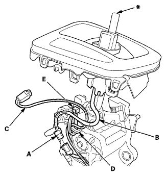
- Connect the D3 switch connector (A). Route the D3 switch harness (B) and the A/T gear position indicator panel light harness (C) along with the shift lever assembly, and tie the harnesses at the guide (D) with the harness wire tie (E)
 Courtesy of AMERICAN HONDA MOTOR CO., INC.
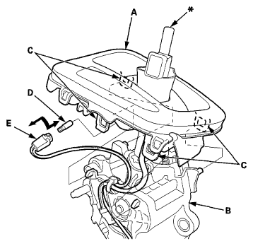
- Install the A/T gear position indicator panel assembly (A) on the shift lever assembly (B) by aligning the four lock tabs (C).
 Courtesy of AMERICAN HONDA MOTOR CO., INC.
- Install the bulb (D) in the A/T gear position indicator panel light socket (E), then install the socket in the indicator panel.
- Install the shift lever knob (see SHIFT LEVER KNOB AND SHIFT LEVER KNOB COVER REPLACEMENT
).
- Install the shift lever assembly (see SHIFT LEVER REMOVAL
).