Telematics Control Unit Connector For Inputs And Outputs (2019 2020 2021)
| Connector Index |
| Telematics Control Unit Connector A (32P) |
| Telematics Control Unit Connector B (5P) |
| Telematics Control Unit Connector C (4P) |
| Telematics Control Unit Connector D (2P) |
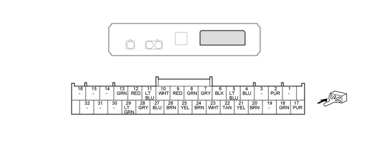
Telematics Control Unit Connector A (32P) (female terminals)
 Courtesy of HONDA, U.S.A., INC. Courtesy of HONDA, U.S.A., INC.
|
| Cavity |
Terminal Name |
Description |
| A1 |
Not used |
- - - |
| A2 |
ACC (DC/DC) |
Power source for accessories |
| A3 |
Not used |
- - - |
| A4 |
E-CALL SW+ |
Detects signal from LINK/ASSIST buttons |
| A5 |
E-CALL SW- |
LINK/ASSIST buttons ground |
| A6 |
GND |
Ground for telematics control unit (G405) |
| A7 |
SH MIC |
Shield for terminals No. 8 and No. 9 |
| A8 |
MIC GND |
Inputs sound signal from HFL microphone |
| A9 |
MIC SIG |
Inputs sound signal from HFL microphone |
| A10 |
MIC PWR |
Power source for front HFL-ANC/active sound control microphone |
| A11 |
HFT MUTE |
Outputs HFL microphone directivity switching signal |
| A12 |
TELEM SIG+ |
Outputs sound prompts |
| A13 |
TELEM SIG- |
Outputs sound prompts |
| A14 |
Not used |
- - - |
| A15 |
Not used |
- - - |
| A16 |
Not used |
- - - |
| A17 |
+B BACKUP(DC/DC) |
Continuous power source |
| A18 |
IG1 METER(DC/DC) |
IG1 power source |
| A19 |
Not used |
- - - |
| A20 |
E-CALL LED RED |
Outputs drive signal for telematics system status indicator LED (red) |
| A21 |
E-CALL LED GREEN |
Outputs drive signal for telematics system status indicator LED (green) |
| A22 |
B-CAN_L |
Communication signal |
| A23 |
B-CAN_H |
Communication signal |
| A24 |
TEL MUTE ICU |
Outputs audio system mute signal |
| A25 |
MIC SIG+ |
Outputs Voice Recognition (VR) prompts |
| A26 |
MIC SIG- |
Outputs Voice Recognition (VR) prompts |
| A27 |
MIC MUTE |
Inputs HFL microphone directivity switching signal |
| A28 |
SH TELEM SIG |
Shield for terminals No. 12 and No. 13 |
| A29 |
CDS |
Inputs collision detection signal |
| A30 |
Not used |
- - - |
| A31 |
Not used |
- - - |
| A32 |
Not used |
- - - |
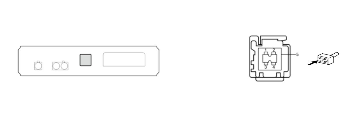
Telematics Control Unit Connector B (5P) (female terminals)
 Courtesy of HONDA, U.S.A., INC. Courtesy of HONDA, U.S.A., INC.
|
| Cavity |
Terminal Name |
Description |
| B1 |
USB GND |
Ground for USB |
| B2 |
USB VBUS |
Outputs power source for USB |
| B3 |
USB DATA+ |
Communication signal |
| B4 |
USB DATA- |
Communication signal |
| B5 |
USB SH |
Shield for terminals No. 1, No. 2, No. 3, and No. 4 |
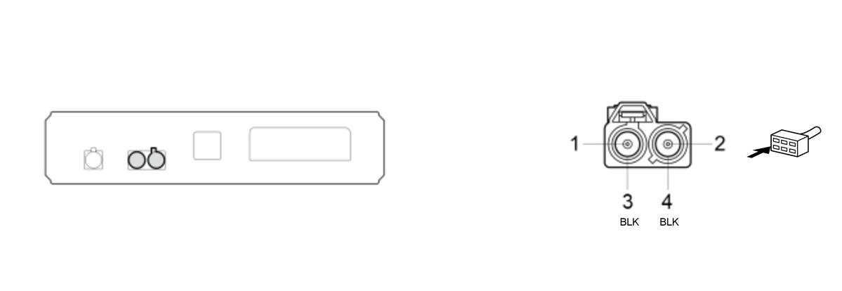
Telematics Control Unit Connector C (4P) (female terminals)
 Courtesy of HONDA, U.S.A., INC. Courtesy of HONDA, U.S.A., INC.
|
| Cavity |
Terminal Name |
Description |
| C1 |
TEL 1 |
Cellular communication signal (Primary) |
| C2 |
GPS TCU |
Inputs GPS signal |
| C3 |
SH (TEL 1) |
Shield for terminal No. 1 |
| C4 |
SH (GPS TCU) |
Shield for terminal No. 2 |
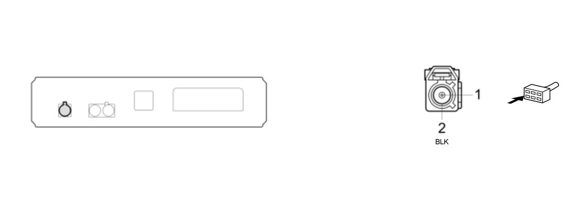
Telematics Control Unit Connector D (2P) (female terminals)
 Courtesy of HONDA, U.S.A., INC. Courtesy of HONDA, U.S.A., INC.
|
| Cavity |
Terminal Name |
Description |
| D1 |
TEL ANT 2 |
Cellular communication signal (Secondary) |
| D2 |
SH (TEL ANT 2) |
Shield for terminal No. 1 |