DTC P1220: Fuel Pump Control Module (FPCM): Procedure
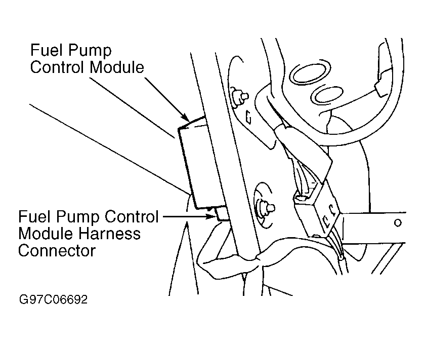
- Turn ignition off. Disconnect FPCM harness connector. See Fig 1. Turn ignition on. Measure voltage between ground and FPCM harness connector terminal No. 3 (Black/Yellow wire). If battery voltage exists, go to next step. If battery voltage does not exist, repair open or short circuit. See appropriate diagram in WIRING DIAGRAMS article.
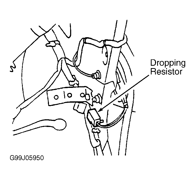
- Disconnect dropping resistor harness connector. See Fig 2. Check continuity between ground and dropping resistor harness connector Black wire. Also check continuity between ground and FPCM harness connector terminal No. 2 (Black wire). If continuity exists, go to next step. If continuity does not exist, repair open ground circuit. See appropriate diagram in WIRING DIAGRAMS article.
- Disconnect fuel pump harness connector located in luggage compartment. Check continuity of Green/Red wire between FPCM harness connector terminal No. 1, fuel pump harness connector and dropping resistor harness connector. If continuity exists, go to next step. If continuity does not exist, repair open in Green/Red wire.
- Check continuity between ground and FPCM harness connector terminals No. 1 (Green/Red wire) and No. 3 (Black/Yellow wire). If continuity does not exist, go to next step. If continuity exists, repair short to ground.
- Disconnect PCM harness connector. See Figure. Check continuity of Red/Blue wire between FPCM harness connector terminal No. 4 and PCM harness connector terminal No. 15. See Figure. If continuity exists, go to next step. If continuity does not exist, repair open in Red/Blue wire.
- Check continuity of Green/Red wire between PCM harness connector terminal No. 93, fuel pump harness connector and dropping resistor harness connector. If continuity exists, go to next step. If continuity does not exist, repair open in Green/Red wire.
- Measure resistance between dropping resistor terminals. Resistance should be .8 ohm at 77°F (25°C). Replace dropping resistor if resistance is not as specified. If dropping resistor is okay, reconnect all harness connectors. Start engine and warm to normal operating temperature. Turn ignition off and wait at least 5 seconds. Start engine and let it idle. Go to next step.
- Measure voltage between FPCM harness connector terminals No. 1 (Green/Red wire) and No. 2 (Black wire) by backprobing. For 30 seconds after starting engine, voltage should be about zero volts. After 30 seconds, voltage should be about 4.4 volts. If voltage is not as specified, replace FPCM. If voltage is as specified, no problem is indicated at this time. Problem may be intermittent. See TESTING PROCEDURE under SELF-DIAGNOSTIC SYSTEM in SELF-DIAGNOSTICS - INTRODUCTION article.
 Courtesy of NISSAN MOTOR CO., U.S.A.
 Courtesy of NISSAN MOTOR CO., U.S.A.