Diagnostic Procedures
- Perform OBD-II system check. See ON-BOARD DIAGNOSTIC II (OBD-II) SYSTEM CHECK
. After performing OBD-II system check, go to next step.
- With ignition on and engine off, review and record FAILURE RECORDS data on scan tool, then clear DTCs. Operate vehicle within conditions noted in FAILURE RECORDS data. Monitor specified DTC information. If scan tool indicates DTC P0106 RAN AND PASSED, go to next step. If scan tool does not indicate DTC P0106 RAN AND PASSED, go to step 4
.
- Check for following conditions: vacuum hoses disconnected, damaged or incorrectly routed, intake manifold vacuum leaks, throttle body leaks, and EGR valve flange and pipe leaks. Repair as necessary. Retest system. If no problem is found, see DIAGNOSTIC AIDS
.
- Disconnect MAP sensor connector and observe MAP value displayed on scan tool. Normal reading is zero volts and 10.3 kPa. If reading is as specified, go to step 6
. If reading is not as specified, go to next step.
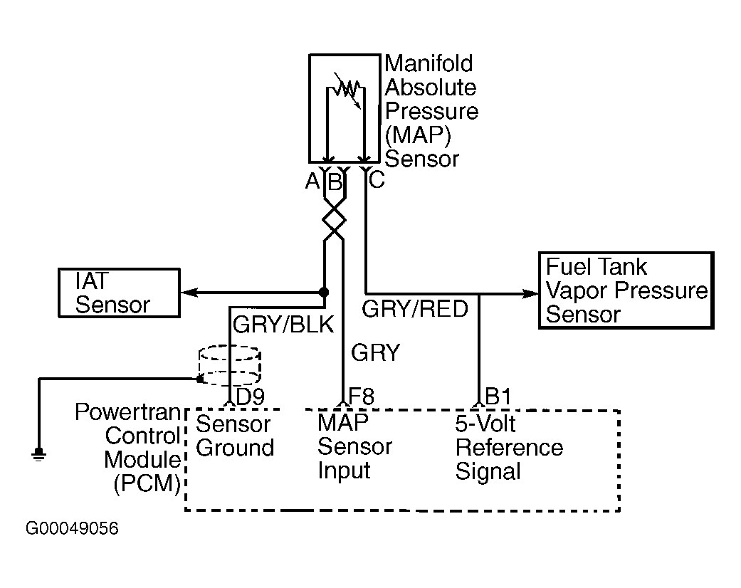
- Turn ignition off. Disconnect PCM harness connectors. Turn ignition on. Using DVOM, check for short to voltage in MAP sensor input circuit (Gray wire) between MAP sensor connector and PCM harness connector terminal F8. See Figure
and Fig 1
. If voltage is present, locate short to voltage and repair as necessary. If no voltage is present, go to step 12
.
- Turn ignition off. Disconnect PCM harness connectors. Using DVOM, check MAP sensor input circuit (Gray wire) between MAP sensor connector and PCM harness connector terminal F8 for open circuit or short to ground. See Figure
and Fig 1
. Repair as necessary. If no problem was found, go to next step.
- Connect PCM harness connectors. Turn ignition on. Check MAP sensor connector 5-volt reference terminal (Gray/Red wire) for voltage. If reading indicates about 5 volts, go to next step. If reading does not indicate about 5 volts, locate and repair open or shorted condition in 5-volt reference circuit.
- Turn ignition off. Using fused jumper wire, connect Gray/Red and Gray wires together at MAP sensor harness connector. Turn ignition on. Observe MAP value displayed on scan tool. If reading is about 5 volts and 104 kPa, go to next step. If reading is not as specified, go to step 12
.
- Turn ignition off. Disconnect PCM harness connectors. Check for open or short to voltage in MAP sensor ground circuit (Gray/Black wire) between MAP sensor connector and PCM harness connector terminal D9. See Figure
and Fig 1
. Repair as necessary. If no problem was found, go to next step.
- Connect PCM harness connectors. Connect DVOM positive lead to MAP sensor connector Gray/Red wire (5-volt reference), and negative lead to MAP sensor connector Gray/Black wire (ground). Turn ignition on. If reading indicates about 5 volts, go to next step. If reading does not indicate about 5 volts, go to step 12
.
- Replace MAP sensor. Retest system.
- Replace and reprogram PCM using required equipment. See PROGRAMMING
. Retest system.
 Courtesy of ISUZU MOTOR CO.