September 30: LEMON manuals is back up on a temporary server! Slowness is possible
Chime Inoperative With Driver's Seat Belt Unfastened
- Ensure driver's seat belt is unfastened. Using scan tool, select BODY, BODY COMPUTER and INPUT/OUPUT. Turn ignition on. Read SEAT BELT SW status on scan tool. If scan tool does not indicate SEAT BELT SW: CLOSED, go to next step. If scan tool indicates SEAT BELT SW: CLOSED, replace Body Control Module (BCM). See BODY CONTROL MODULE under REMOVAL & INSTALLATION. Perform BODY VERIFICATION TEST under VERIFICATION TESTS.
- Disconnect seat belt switch 2-pin connector located at base of driver's seat belt buckle. Monitor scan tool display. Connect a fused jumper wire between seat belt switch connector terminals No. 1 (Light Green/Red wire) and No. 2 (Black wire). If scan tool does not indicate SEAT BELT SW: CLOSED, go to next step. If scan tool indicates SEAT BELT SW: CLOSED, replace seat belt switch. Perform BODY VERIFICATION TEST under VERIFICATION TESTS.
- Connect a fused jumper wire between seat belt switch connector terminal No. 1 (Light Green/Red wire) and ground. Monitor scan tool display. If scan tool does not indicate SEAT BELT SW: CLOSED, go to next step. If scan tool indicates SEAT BELT SW: CLOSED, repair open in Black wire between seat belt switch and ground. Perform BODY VERIFICATION TEST under VERIFICATION TESTS.
- Access junction block connector C1. See Fig 1. Do not disconnect any connectors. Use a jumper wire to backprobe junction block connector C1 between terminal No. 19 (Light Green/Red wire) and ground. See Fig 2. Monitor scan tool display. If scan tool does not indicate SEAT BELT SW: CLOSED, go to next step. If scan tool indicates SEAT BELT SW: CLOSED, repair open in Light Green/Red wire between seat belt switch and junction block connector C1. Perform BODY VERIFICATION TEST under VERIFICATION TESTS.
- Turn ignition off. With jumper wire still connected, remove BCM from rear of junction block. See Figure. Using DVOM, measure resistance between BCM junction block connector terminal No. 22 and ground. See Fig 3. If resistance is less than 5 ohms, replace BCM. See BODY CONTROL MODULE under REMOVAL & INSTALLATION. Perform BODY VERIFICATION TEST under VERIFICATION TESTS. If resistance is greater than 5 ohms, test is complete.
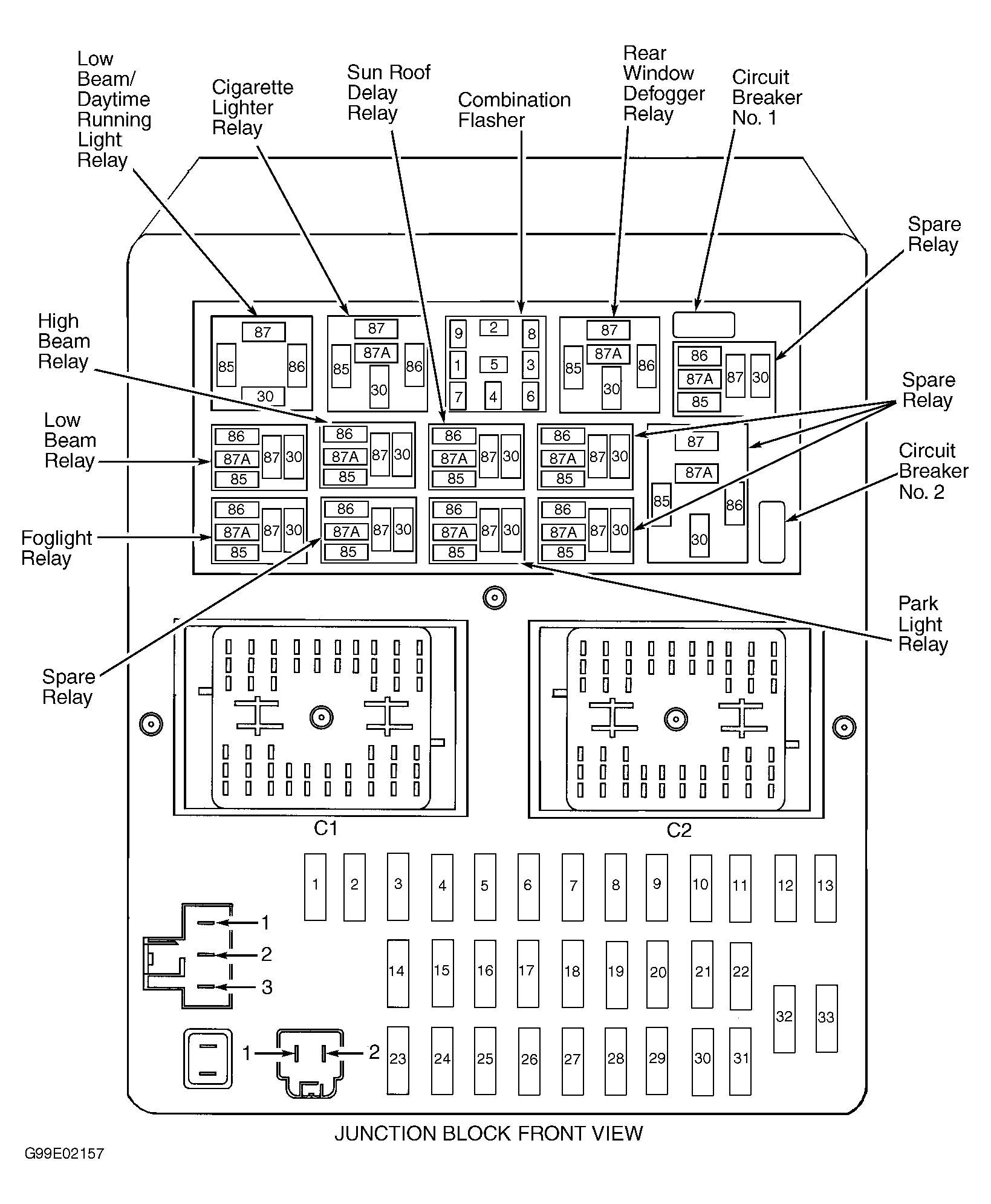 Courtesy of CHRYSLER CORP.
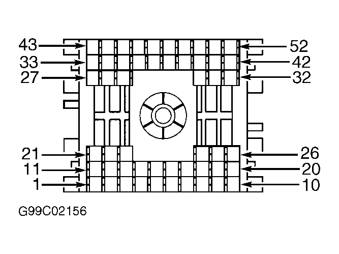 Courtesy of CHRYSLER CORP.
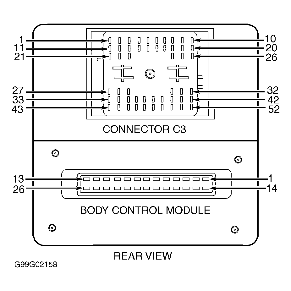 Courtesy of CHRYSLER CORP.