September 30: LEMON manuals is back up on a temporary server! Slowness is possible
Wiper Erratic Operation In Intermittent Speeds
- Turn ignition off. Disconnect junction block connector C2. Disconnect Body Control Module (BCM) from junction block. See Figure and Figure
. Using DVOM, measure resistance between BCM junction block connector terminal No. 20 and junction block connector C2 terminals No. 28 and 30. See Figure and Figure
. If resistance is less than 5 ohms on both circuits, go to next step. If resistance is 5 ohms or greater on either circuit, replace junction block. Perform BODY VERIFICATION TEST under VERIFICATION TESTS.
- Remove wiper on/off relay from Power Distribution Center (PDC). See Figure. Energize relay by applying battery voltage to terminal No. 85 and ground terminal No. 86 of relay. See Fig 1. Check continuity between relay terminals No. 30 and 87. If continuity is present, go to next step. If continuity is not present, replace relay. Perform BODY VERIFICATION TEST under VERIFICATION TESTS.
- Using DVOM, measure resistance of Tan/Red wire between junction block connector C2 terminal No. 33 and wiper on/off relay socket terminal No. 87A. If resistance is less than 5 ohms, go to next step. If resistance is 5 ohms or greater, repair open in Tan/Red wire. Perform BODY VERIFICATION TEST under VERIFICATION TESTS.
- Disconnect wiper motor connector. Using DVOM, measure resistance of Tan/Red wire between junction block connector C2 terminal No. 28 and wiper motor connector terminal No. 2. See Figure. If resistance is less than 5 ohms, go to next step. If resistance is 5 ohms or greater, repair open in Tan/Red wire. Perform BODY VERIFICATION TEST under VERIFICATION TESTS.
- Turn ignition off. Remove BCM from rear of junction block. Disconnect BCM connector C1. Connect a jumper wire between ground and BCM connector C1 terminal No. 22 (Red/Violet wire). Connect test light between ground and terminal No. 20 on BCM junction block connector. Turn ignition on. Turn wiper switch to a position where wiper are working properly and observe test light. If test light does not pulse, go to next step. If test light pulses, replace BCM. See BODY CONTROL MODULE under REMOVAL & INSTALLATION. Perform BODY VERIFICATION TEST under VERIFICATION TESTS.
- Turn ignition on. Using DVOM, measure voltage between ground and wiper motor connector terminal No. 1 (Dark Blue wire). If voltage is greater than 10 volts, go to next step. If voltage is less than 10 volts, repair open in Dark Blue wire between wiper motor and junction block. Perform BODY VERIFICATION TEST under VERIFICATION TESTS.
- Ensure all connectors are connected. Using test light, backprobe wiper motor connector between ground and terminal No. 2 (Tan/Red wire). Turn wiper switch to a position where wiper are working properly and observe test light. If test light pulses, go to test is complete. If test light does not pulse, replace wiper motor. See appropriate
WIPER/WASHER SYSTEMS article. Perform BODY VERIFICATION TEST under VERIFICATION TESTS.
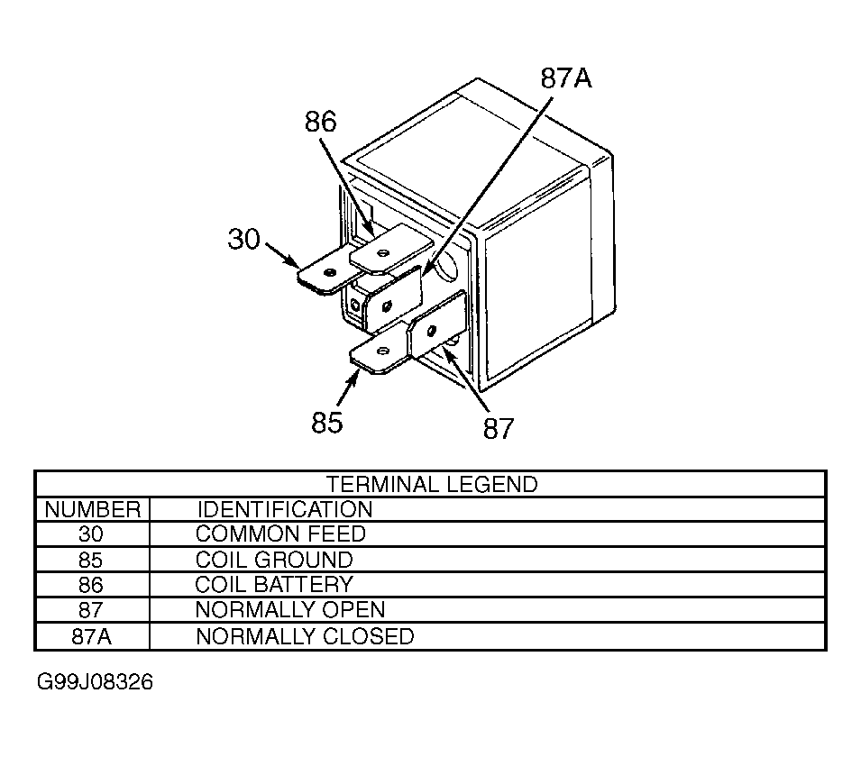 Courtesy of CHRYSLER CORP.