6F24 Automatic Transmission (Service Information): Installation: AWD
- While guiding the transaxle past obstacles, raise the transaxle upward until the transaxle is in line with the engine.
 Courtesy of CHRYSLER GROUP, LLC
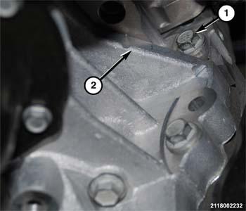
- Place the bellhousing (1) in position against the engine block (2).
- Install the bolt (1) to hold the front of the engine block to the bellhousing. Refer to SPECIFICATIONS .
 Courtesy of CHRYSLER GROUP, LLC
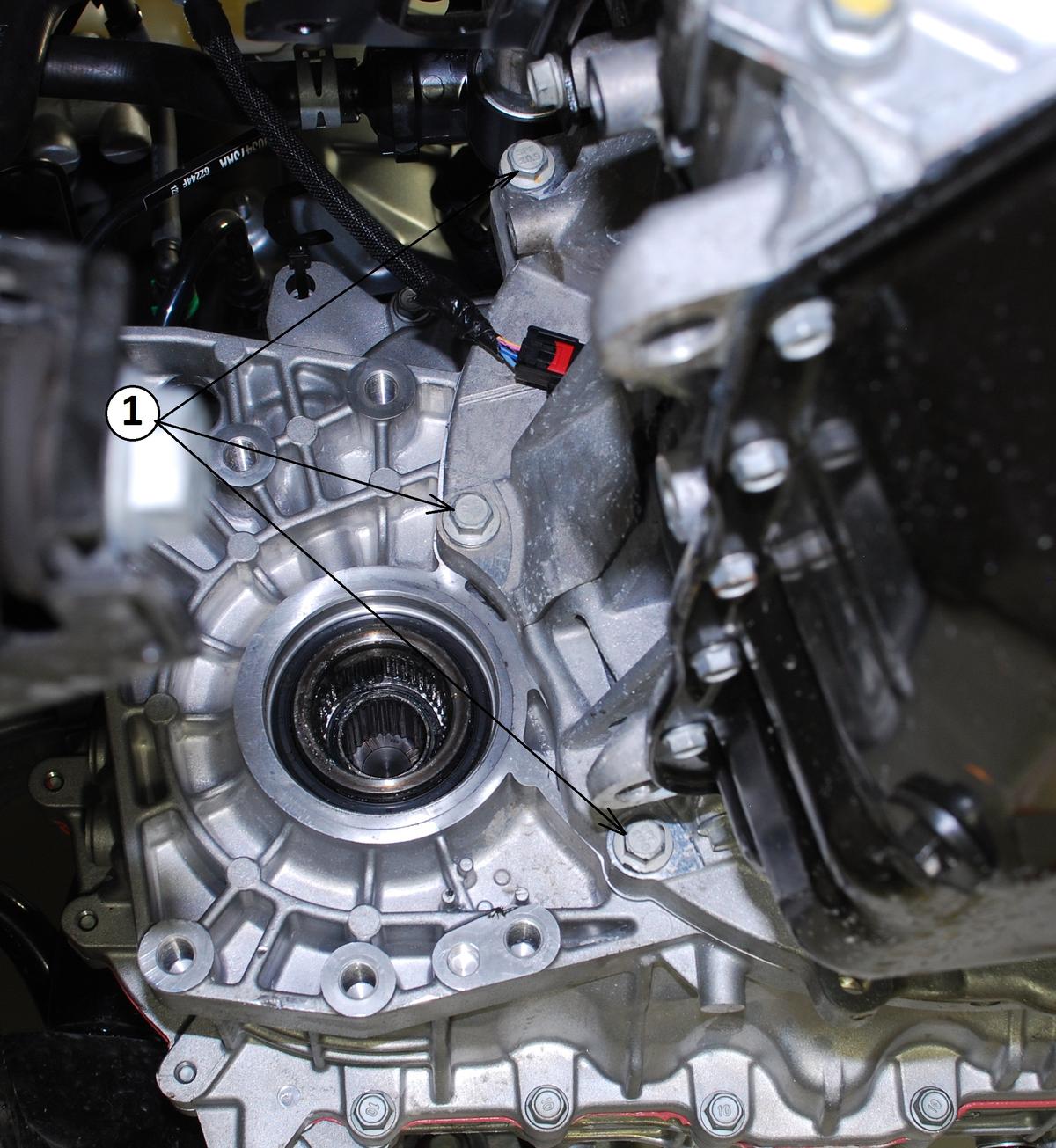
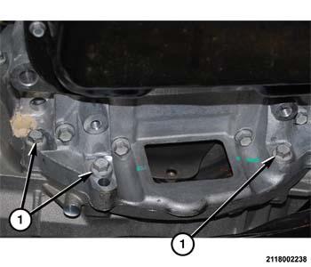
- Install the bolts (1) to hold the rear of the engine block to the bellhousing. Refer to SPECIFICATIONS .
 Courtesy of CHRYSLER GROUP, LLC
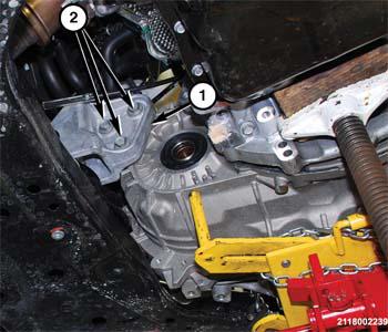
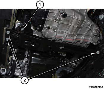
- Place the rear mount (1) in position (typical) and install the bolts (2) to hold the rear transaxle mount (1) to the back of the transaxle. Refer to SPECIFICATIONS .
 Courtesy of CHRYSLER GROUP, LLC
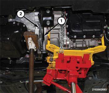
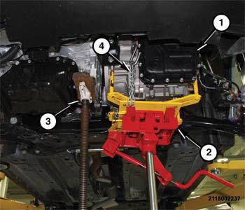
- Lower the transaxle (1) so all of the weight is bearing on the high-stand (3).
- Remove the safety chine (4) holding the transaxle (1) to the jack cradle.
- Lower and remove the transmission jack (2) from under the transaxle.
 Courtesy of CHRYSLER GROUP, LLC
- Place the front-to-rear support in position on the vehicle.
- Install the bolts (2) to hold the front-to-rear support to the front and rear crossmembers. Refer to SPECIFICATIONS .
- Install the trough bolt (1) to hold the front-to-rear support rubber isolator to the front crossmember. Refer to SPECIFICATIONS .
- Remove the high-stand (3) from under the engine.
 Courtesy of CHRYSLER GROUP, LLC
- Install the bolts (1) to hold the lower engine adapter to the bellhousing. Refer to SPECIFICATIONS .
 Courtesy of CHRYSLER GROUP, LLC
- Install the bolt (1) to hold the engine block (2) to the bellhousing next to the starter motor. Refer to SPECIFICATIONS .
 Courtesy of CHRYSLER GROUP, LLC
- Install the bolts (2) to hold the flex plate to the torque converter. Refer to SPECIFICATIONS .
 Courtesy of CHRYSLER GROUP, LLC
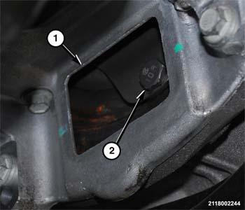
- Install the torque converter bolt access plug (2) into the bellhousing cover.
- Install the power transfer unit (PTU). Refer to INSTALLATION
.
- Install the left and right halfshafts. Refer to INSTALLATION
.
- Fill the transaxle to the proper level.
- Install the belly pan. Refer to BELLY PAN, INSTALLATION
.
- Lower the vehicle.
 Courtesy of CHRYSLER GROUP, LLC
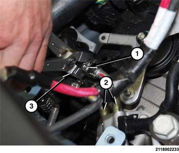
- Push the hoses (1) onto the cooler tubes (2) on the transaxle.
 Courtesy of CHRYSLER GROUP, LLC
- Using a suitable clamp pliers (3), crimp the clamps (1) to hold the transaxle cooler hoses to the tubes (2) on the transaxle.
 Courtesy of CHRYSLER GROUP, LLC
- Place the transaxle mount in position on the vehicle.
- Position a suitable floor jack under the left (driver) side of the transaxle to add support.
- Raise the transaxle until the bolt holes for the transaxle mount line up.
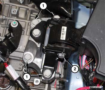
- Install the bolts (1) to hold the transaxle mount to the transaxle. Refer to SPECIFICATIONS .
- Install the through bolt (2) to hold the transaxle mount rubber isolator to the frame rail bracket. Refer to SPECIFICATIONS .
 Courtesy of CHRYSLER GROUP, LLC
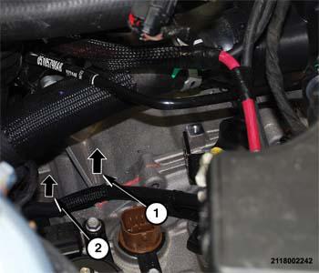
- Install the hidden bolts (1, 2) to hold the starter motor to the engine block and bellhousing. Refer to SPECIFICATIONS .
 Courtesy of CHRYSLER GROUP, LLC
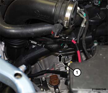
- Install the hidden bolt (1) to hold the ground cable and transaxle bellhousing to the engine block under the engine coolant tubes. Refer to SPECIFICATIONS .
 Courtesy of CHRYSLER GROUP, LLC
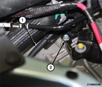
- Place the vent tube (1) in position on the transaxle.
- Install the bolt (2) to hold the vent tube (1) to the transaxle. Refer to SPECIFICATIONS .
 Courtesy of CHRYSLER GROUP, LLC
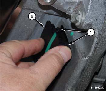
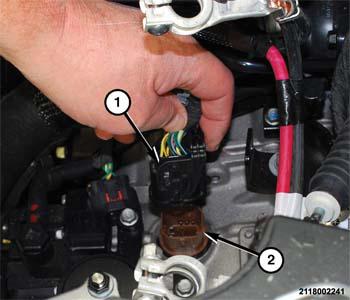
- Engage the wire harness connector into the TRS (1).
- Push inward until the lock (2) clicks into position.
 Courtesy of CHRYSLER GROUP, LLC
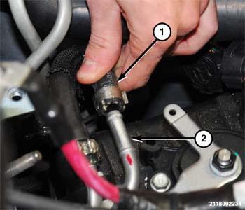
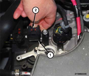
- Engage the wire harness connector (1) into the solenoid connector on the transaxle.
- Set the lock on the transaxle solenoid connector (1).
- Insert the shift cable into the bracket on the top of the transaxle and engage the locking clips.
- Place the shift cable (adjuster screw up) on the manual lever pin.
- Push downward on the shift cable end until it locks on the manual lever pin.
 Courtesy of CHRYSLER GROUP, LLC
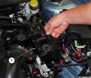
- Place the lower air cleaner bracket (1) in position on the vehicle.
 Courtesy of CHRYSLER GROUP, LLC
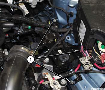
- Install the bolts and nuts (1) to hold the lower air cleaner bracket to the left frame rail. Refer to SPECIFICATIONS .
- Install the lower air cleaner body. Refer to 2.0L BODY, AIR CLEANER, INSTALLATION
, or 2.4L BODY, AIR CLEANER, INSTALLATION
.
- Install the air box lid.
- Install the battery tray in the vehicle. Refer to TRAY, BATTERY, INSTALLATION
.
- Install the battery in the vehicle. Refer to BATTERY, INSTALLATION
.
- Install the engine air-box in the vehicle.
- Secure the fasteners to hold the engine air-box to the front crossmember.
- Close the hood.
- Road test the vehicle to verify the repair.