Test Procedure
- Turn ignition off. Connect Hi-Scan Pro/Kia Data Pro Scan tool or equivalent to OBD-II Data Link Connector. See Figure. Turn ignition on. Monitor for other DTCs. If other DTCs are set, do all repairs associated with those DTCs before continuing with this procedure. If no other DTCs are set, go to next step.
- Start engine. Allow engine to idle until reaches normal operating temperature for more than 10 minutes. Using Hi-Scan Pro/Kia Data Pro Scan tool or equivalent, monitor right front HO2S voltage signal waveform. See Fig 1. If HO2S voltage signal switches from lean to rich or rich to lean over 6 times for 10 seconds, problem is intermittent. Check HO2S and ECM for proper harness connections and go to step 7. If voltage signal waveform is not as specified, go to next step.
- Turn ignition off. Disconnect right front HO2S 4-pin harness connector. See Fig 2 and ECM harness connector "P". See Figure. Measure resistance between HO2S connector terminal No. 1 (Tan wire) and ECM connector terminal P20. Also measure resistance between HO2S connector terminal No. 2 (Violet wire) and ECM connector terminal P14. Both resistances should be below one ohm. If resistances are as specified, go to next step. If any resistance is not as specified, repair open circuit as necessary and go to step 7.
- With right front HO2S and ECM harness connectors disconnected. Turn ignition on. Measure voltage between ground and HO2S connector terminal No. 2 (Violet wire). Voltage should be below 0.5 volts. If voltage is as specified, go to next step. If voltage is not as specified, repair short circuit as necessary and go to step 7.
- Turn ignition off. With right front HO2S harness connector and ECM harness connectors disconnected. Measure resistance between ground and HO2S connector terminal No. 2 (Violet wire). Also measure resistance between HO2S connector terminals No. 1 (Tan wire) and No. 2 (Violet wire). Measure resistance between terminal No. 1 (Tan wire) and No. 3 (Pink wire). Measure resistance between terminal No. 1 (Tan wire)and No. 4 (Pink wire). Measure resistance between terminal No. 2 (Violet wire) and No. 3 (Pink wire). Measure resistance between terminal No. 2 (Violet wire) and No. 4 (Pink wire). Measure resistance between terminal No. 3 (Pink wire) and No. 4 (Pink wire). All resistances should be infinite. If resistances are as specified, go to next step. If any resistance is not as specified, repair short circuit as necessary and go to step 7.
- Remove right front HO2S from vehicle, check HO2S for contamination, deterioration or damage. If HO2S is contaminated, deteriorated or damage, replace HO2S and go to next step. If HO2S seems okay, temporarily install a known-good HO2S and check for proper operation. If problem is corrected, replace HO2S sensor and go to next step.
- After repair, return vehicle to original condition. Clear codes using Hi-Scan Pro/Kia Data Pro Scan tool or equivalent. Verify repairs by driving vehicle and monitoring for pending codes. If DTC is set during test drive, follow appropriate DTC test procedure.
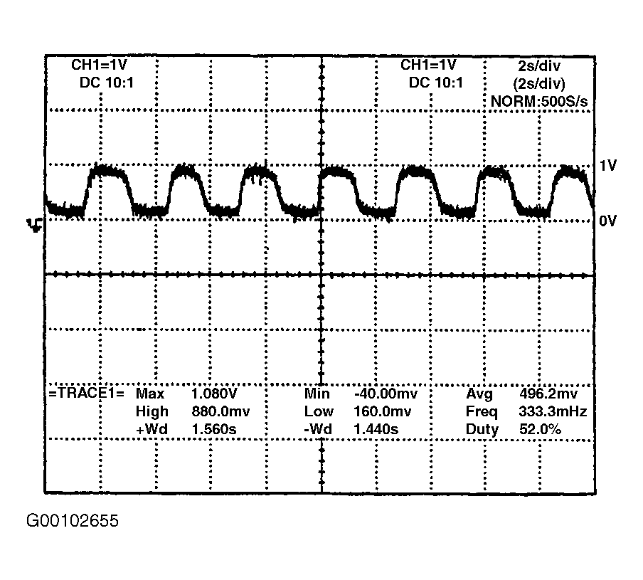 Courtesy of KIA MOTORS AMERICA, INC.
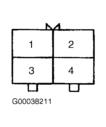 Courtesy of KIA MOTORS AMERICA, INC.