Selector Lever Cable: Installation
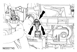
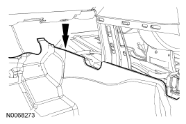
- Position the selector lever cable in the vehicle and install the cable in the bracket.
- Be sure the tabs are locked in place.
 Courtesy of FORD MOTOR CO.
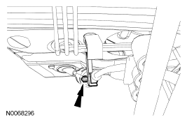
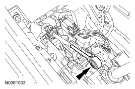
- Connect the selector lever cable retainer on the brake tube bracket.
 Courtesy of FORD MOTOR CO.
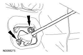
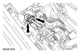
- Install the selector lever cable, position the grommet in place and install the 2 nuts.
- Tighten to 7 Nm (62 lb-in).
 Courtesy of FORD MOTOR CO.
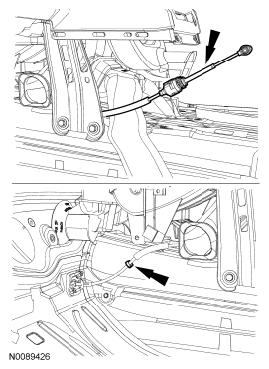
- Route the selector lever cable under the heater housing and connect the selector lever cable retainer to the center console.
 Courtesy of FORD MOTOR CO.
- Position the floor console finish panel in place.
 Courtesy of FORD MOTOR CO.
- Install the selector lever cable on the selector lever housing.
- Be sure the tabs are locked in place.
 Courtesy of FORD MOTOR CO.
- Connect the selector lever cable end on the selector lever.
 Courtesy of FORD MOTOR CO.
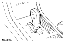
- Place the selector lever in DRIVE.
 Courtesy of FORD MOTOR CO.
- Place the manual control lever in DRIVE.
- Rotate the manual control lever clockwise until it stops.
- Rotate the manual control lever counterclockwise one detent.
 Courtesy of FORD MOTOR CO.
- Unlock the adjuster by sliding the locking tab over.
 Courtesy of FORD MOTOR CO.
- Slide the selector lever cable end forward or backward to align it with the manual control lever.
 Courtesy of FORD MOTOR CO.
- With the adjuster locking tab unlocked, connect the selector lever cable end to the manual control lever.
 Courtesy of FORD MOTOR CO.
- Slide the adjuster tab to the LOCK position.
 Courtesy of FORD MOTOR CO.
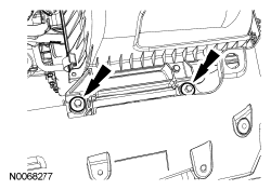
- Position the ACL
assembly in place and install the 2 bolts.
- Tighten to 11 Nm (97 lb-in).
 Courtesy of FORD MOTOR CO.
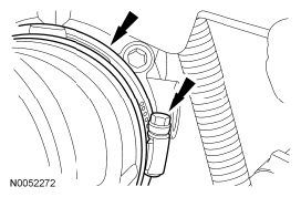
- Tighten the ACL
outlet pipe at the TB
.
- Tighten to 5 Nm (44 lb-in).
 Courtesy of FORD MOTOR CO.
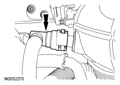
- Connect the engine breather to the ACL
assembly.
 Courtesy of FORD MOTOR CO.
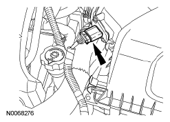
- Connect the MAF
sensor electrical connector.
 Courtesy of FORD MOTOR CO.
- Install the selector lever bezel and selector lever knob. For additional information, refer to SELECTOR LEVER BEZEL and SELECTOR LEVER KNOB .
- Verify that the vehicle starts in PARK and NEUTRAL only and that the reverse lamps illuminate in REVERSE.