SAS Control Module Connector Cover Removal/Installation [Standard Deployment Control System]: Removal
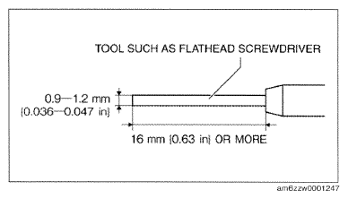
- Obtain a tool such as a flathead screwdriver of the dimensions shown in the figure.
- Switch the ignition off.
- Disconnect the negative battery cable and wait for 1 min or more.
(See
NEGATIVE BATTERY CABLE DISCONNECTION/CONNECTION [SKYACTIV-G 2.0, SKYACTIV-G 2.5]
.)
- Remove the following parts:
- Upper panel (See
UPPER PANEL REMOVAL
.) (See
UPPER PANEL INSTALLATION
.)
- Rear console (See
REAR CONSOLE REMOVAL/INSTALLATION
.)
 Courtesy of MAZDA MOTORS CORP.
- Remove the parking brake lever. (See
PARKING BRAKE LEVER REMOVAL/INSTALLATION
.)
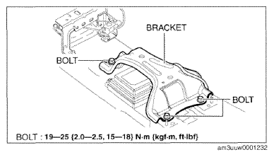
- Remove the bolts.
- Set the bracket out of the way.
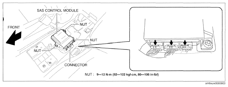
- Remove the nuts.
 Courtesy of MAZDA MOTORS CORP.
 Courtesy of MAZDA MOTORS CORP.
- Remove the SAS control module.
- Disconnect the connectors.
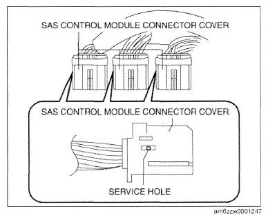
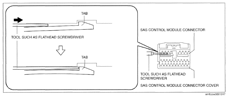
- Insert the flathead screwdriver into the service hole of the SAS control module connector cover in the position shown in the figure.
- Insert the flathead screwdriver in the direction of the arrow shown in the figure until the SAS control module connector cover tab is detached from the SAS control module connector.
 Courtesy of MAZDA MOTORS CORP.
 Courtesy of MAZDA MOTORS CORP.
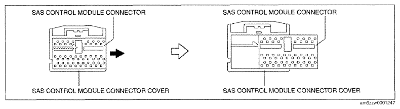
- Pull out the SAS control module connector in the direction of the arrow shown in the figure and remove the SAS control module connector cover.
 Courtesy of MAZDA MOTORS CORP.