Relay And Fuse Block Removal/Installation: Installation
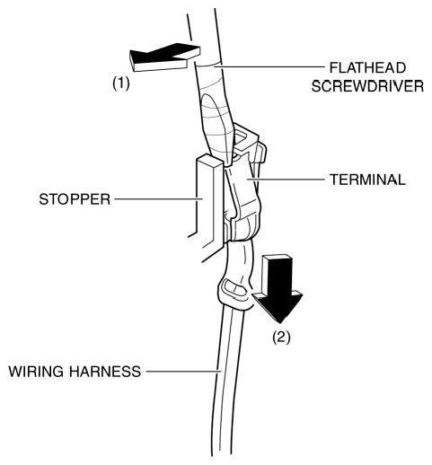
- Move the flathead screwdriver in the direction of the arrow (1) shown in the figure, and pull the wiring harness in the direction of the arrow (2) while pressing the stopper to detach the relay or fuse terminal from the stopper.
 Courtesy of MAZDA MOTORS CORP.
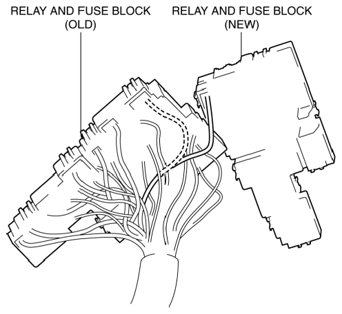
- Relocate all relay and fuse terminals to the new relay and fuse block.
CAUTION:
- If terminals are installed incorrectly, it could damage electrical accessories and burn wiring harnesses. When relocating terminals after replacing the relay and fuse block, line up the relay and fuse blocks of old and news parts and always verify each of the wiring harnesses in the wiring diagram so that the installation positions are correct.
 Courtesy of MAZDA MOTORS CORP.
- A terminal disconnection could cause electronic components and the system to not operate normally due to poor contact. After terminal relocation, lightly pull the wiring harnesses to verify that they cannot be pulled out.
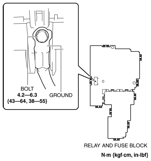
- Install the ground.
 Courtesy of MAZDA MOTORS CORP.
- Install the bolt.
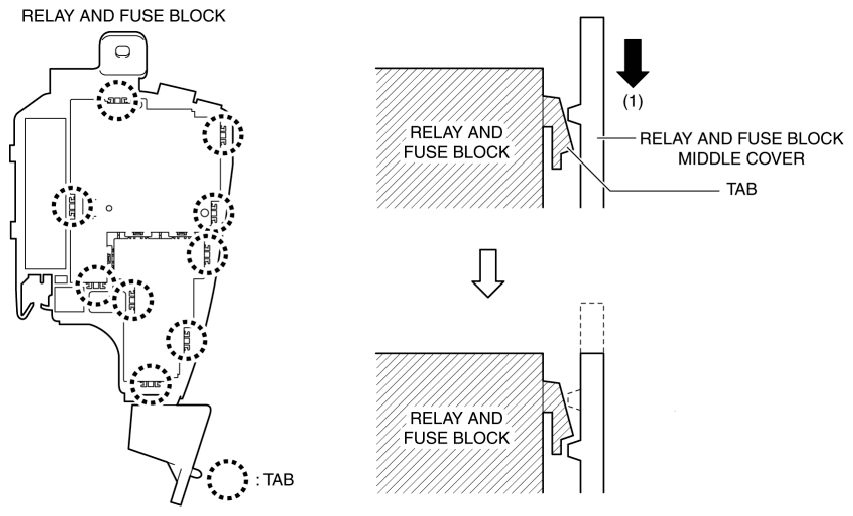
- Move the relay and fuse block middle cover in the direction of arrow (1) shown in the figure and insert the relay and fuse block tab into the relay and fuse block middle cover.
 Courtesy of MAZDA MOTORS CORP.
- Insert all the relay and fuse block tabs into the relay and fuse block middle cover and install the relay and fuse block middle cover.
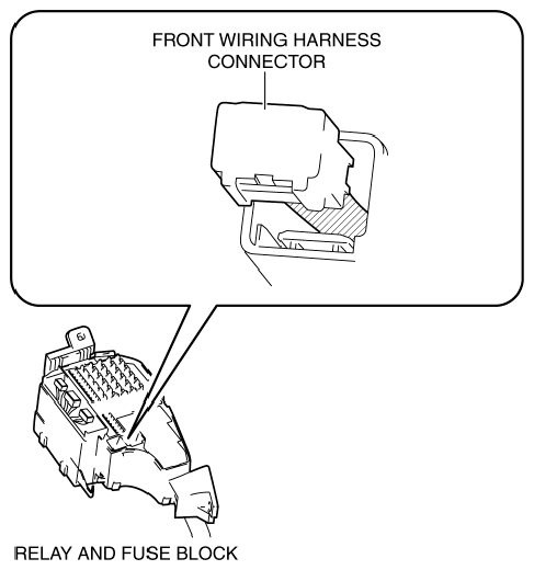
- Insert the front wiring harness connector into the relay and fuse block middle cover.
 Courtesy of MAZDA MOTORS CORP.
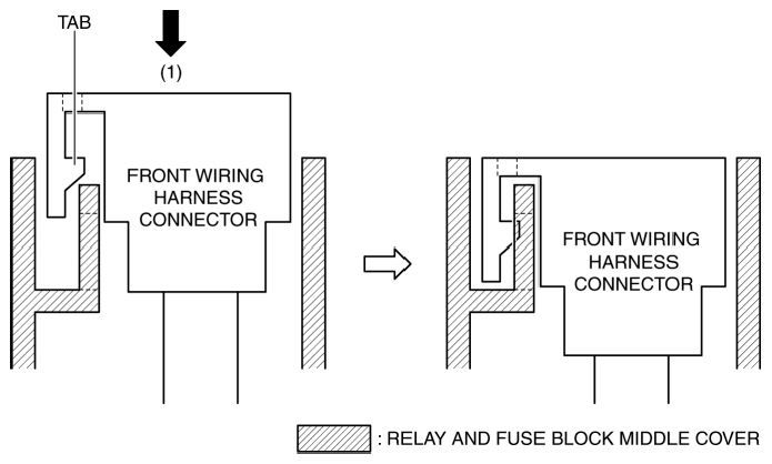
- Move the front wiring harness connector in the direction of arrow (1) shown in the figure to engage the front wiring harness connector tab with the relay and fuse block middle cover.
 Courtesy of MAZDA MOTORS CORP.
- Install all the front wiring harness connectors to the relay and fuse block middle cover.
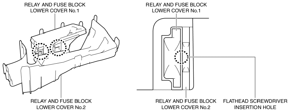
- Insert a flathead screwdriver into the gap between relay and fuse block lower covers No. 1 and 2 shown in the figure.
NOTE:
- When installing the relay and fuse block lower cover to the relay and fuse block middle cover, the wiring harness could get caught between the relay and fuse block middle cover and the relay and fuse block lower cover resulting in open or short circuit in the wiring harness. When installing the relay and fuse block lower cover, disassemble the relay and fuse block lower cover and install one at a time.
 Courtesy of MAZDA MOTORS CORP.
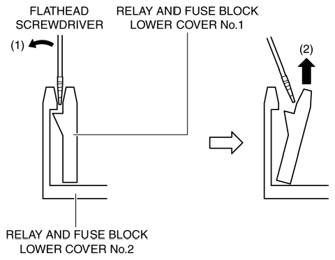
- Move the flathead screwdriver in the direction of the arrow (1) shown in the figure, and pull up relay and fuse block lower cover No. 1 in the direction of the arrow (2) shown in the figure to detach the relay and fuse block lower cover No. 1 tab from relay and fuse block lower cover No. 2.
 Courtesy of MAZDA MOTORS CORP.
- Detach all the relay and fuse block lower cover No. 1 tabs from relay and fuse block lower cover No. 2, and disassemble the relay and fuse block lower cover.
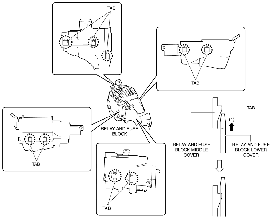
- Move the relay and fuse block lower cover in the direction of arrow (1) shown in the figure and insert the relay and fuse block middle cover tab into the relay and fuse block lower cover.
 Courtesy of MAZDA MOTORS CORP.
- Insert all the relay and fuse block middle cover tabs into the relay and fuse block lower cover and install the relay and fuse block lower cover.
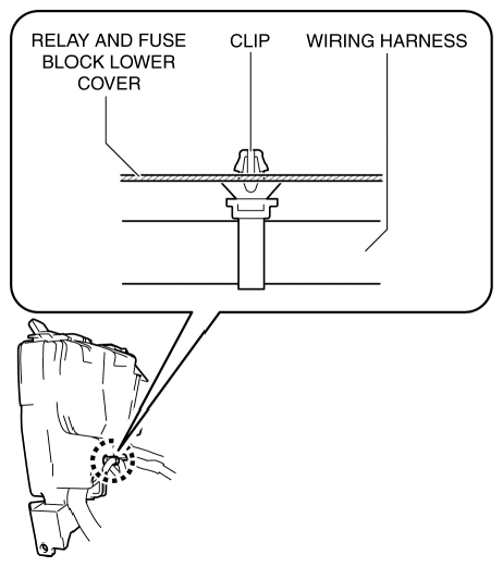
- Install the wiring harness clip to the relay and fuse block lower cover.
 Courtesy of MAZDA MOTORS CORP.
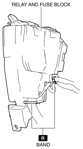
- Install the bands shown in the figure.
 Courtesy of MAZDA MOTORS CORP.
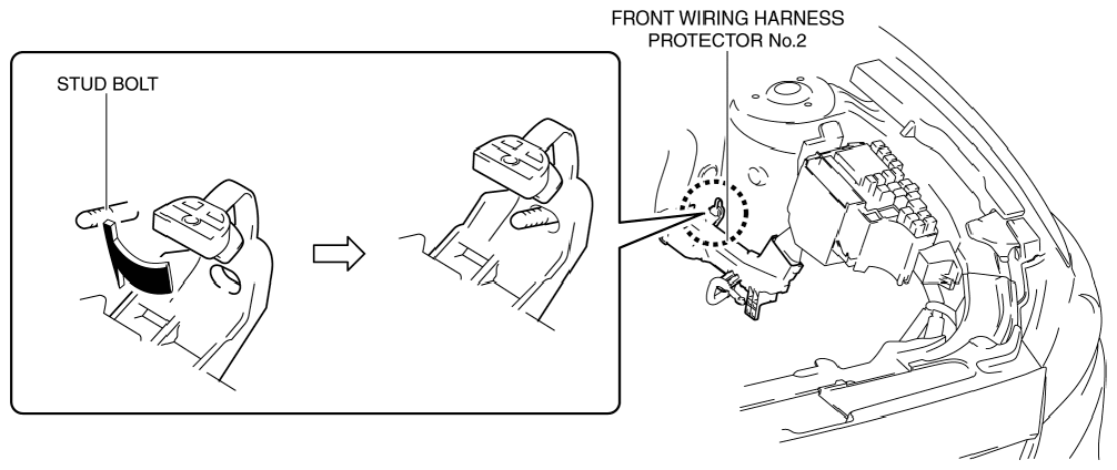
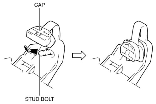
- Insert the front wiring harness protector No. 2 into the stud bolt.
 Courtesy of MAZDA MOTORS CORP.
- Insert the front wiring harness protector No. 2 cap into the stud bolt.
 Courtesy of MAZDA MOTORS CORP.
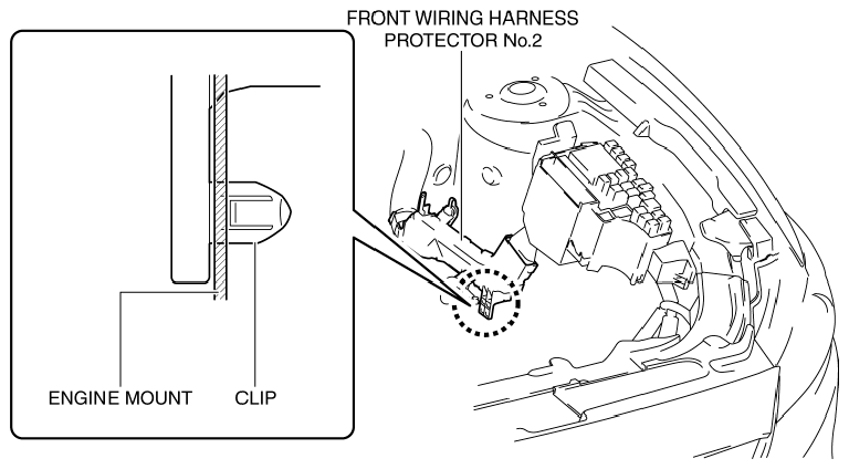
- Install the front wiring harness protector No. 2 clip to the engine mount.
 Courtesy of MAZDA MOTORS CORP.
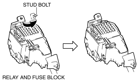
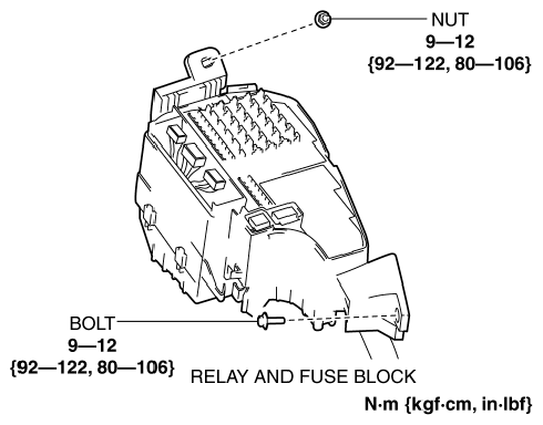
- Insert the relay and fuse block into the stud bolt.
 Courtesy of MAZDA MOTORS CORP.
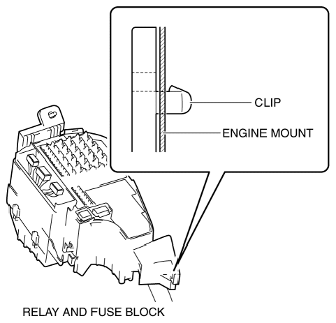
- Insert the relay and fuse block clip into the engine mount.
 Courtesy of MAZDA MOTORS CORP.
- Install the nut and bolt.
 Courtesy of MAZDA MOTORS CORP.
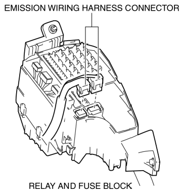
- Connect the emission wiring harness connectors.
 Courtesy of MAZDA MOTORS CORP.
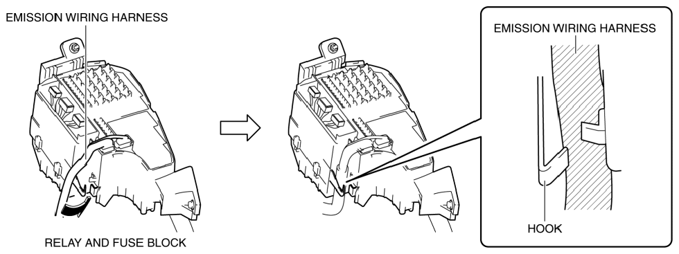
- Press the emission wiring harness into the relay and fuse block hook.
 Courtesy of MAZDA MOTORS CORP.
- Install the front body control module (FBCM). (See FRONT BODY CONTROL MODULE (FBCM) REMOVAL/INSTALLATION
.)
- Install all the relays and fuses.
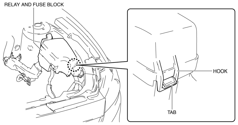
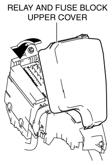
- Engage the relay and fuse block upper cover hook with the relay and fuse block middle cover tab.
 Courtesy of MAZDA MOTORS CORP.
- Install the relay and fuse block upper cover.
 Courtesy of MAZDA MOTORS CORP.
- Install the parts removed in Steps 2 and 3 in "REMOVAL". (See REMOVAL .)
- Perform the "Verify Relay and Fuse Block Replacement". (See VERIFY RELAY AND FUSE BLOCK REPLACEMENT .)
- Connect the negative battery cable. (See NEGATIVE BATTERY CABLE DISCONNECTION/CONNECTION [SKYACTIV-G 2.5]
.)