DTC P0010-00: Electric Variable Valve Timing Control Circuit Range/Performance Problem: Notes
DTC P0010:00 (PCM, SKYACTIV-G 2.5T) DETECTION CONDITION AND POSSIBLE CAUSE
| DTC P0010:00 |
Electric variable valve timing control circuit range/performance problem |
| DETECTION CONDITION |
- Any one of the following conditions is met:
- A malfunction is detected in the results of the on-board diagnostic test received from the electric variable valve timing driver.
- The motor speed signal received from the electric variable valve timing driver is in error.
Diagnostic support note
- This is a continuous monitor (CCM).
- The check engine light illuminates if the PCM detects the above malfunction condition during the first drive cycle.
- FREEZE FRAME DATA/Snapshot data is available.
- DTC is stored in the PCM memory.
|
| FAIL-SAFE FUNCTION |
- Stops activation of the electric variable valve timing driver.
|
| POSSIBLE CAUSE |
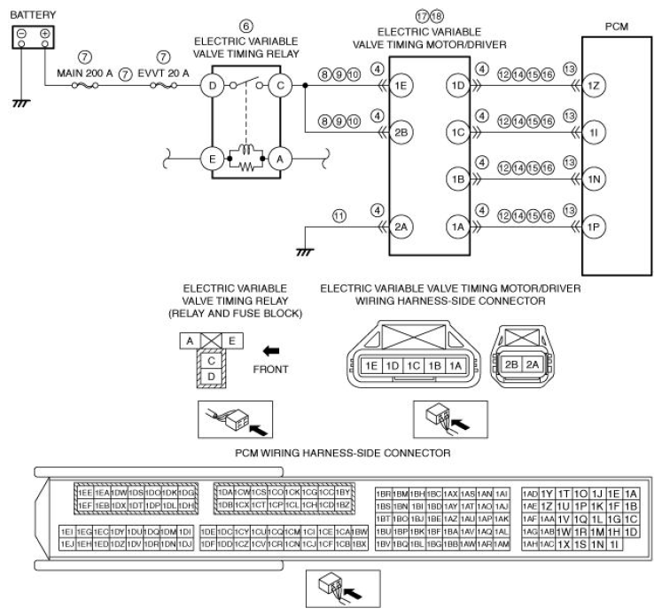
- Electric variable valve timing motor/driver connectors or terminals malfunction
- Electric variable valve timing relay malfunction
- Short to ground or open circuit in electric variable valve timing relay power supply circuit
- Short to ground in wiring harness between MAIN 200 A fuse and electric variable valve timing relay terminal D
- MAIN 200 A fuse and/or EWT 20 A fuse malfunction
- Open circuit in wiring harness between battery positive terminal and electric variable valve timing relay terminal D
- Short to ground in wiring harness between the following terminals:
- Electric variable valve timing relay terminal C-Electric variable valve timing motor/driver terminal 1E
- Electric variable valve timing relay terminal C-Electric variable valve timing motor/driver terminal 2B
- Short to power supply in wiring harness between the following terminals:
- Electric variable valve timing relay terminal C-Electric variable valve timing motor/driver terminal 1E
- Electric variable valve timing relay terminal C-Electric variable valve timing motor/driver terminal 2B
- Open circuit in wiring harness between the following terminals:
- Electric variable valve timing relay terminal C-Electric variable valve timing motor/driver terminal 1E
- Electric variable valve timing relay terminal C-Electric variable valve timing motor/driver terminal 2B
- Open circuit in wiring harness between electric variable valve timing motor/driver terminal 2A and body ground
- Short to ground in wiring harness between the following terminals:
- Electric variable valve timing motor/driver terminal 1D-PCM terminal 1Z
- Electric variable valve timing motor/driver terminal 1C-PCM terminal 1I
- Electric variable valve timing motor/driver terminal 1B-PCM terminal 1N
- Electric variable valve timing motor/driver terminal 1A-PCM terminal 1P
- PCM connector or terminals malfunction
- Short to power supply in wiring harness between the following terminals:
- Electric variable valve timing motor/driver terminal 1D-PCM terminal 1Z
- Electric variable valve timing motor/driver terminal 1C-PCM terminal 1I
- Electric variable valve timing motor/driver terminal 1B-PCM terminal 1N
- Electric variable valve timing motor/driver terminal 1A-PCM terminal 1P
- Electric variable valve timing motor/driver circuits are shorted to each other
- Open circuit in wiring harness between the following terminals:
- Electric variable valve timing motor/driver terminal 1D-PCM terminal 1Z
- Electric variable valve timing motor/driver terminal 1C-PCM terminal 1I
- Electric variable valve timing motor/driver terminal 1B-PCM terminal 1N
- Electric variable valve timing motor/driver terminal 1A-PCM terminal 1P
- Electric variable valve timing driver malfunction
- Electric variable valve timing motor malfunction
- PCM malfunction
|
 Courtesy of MAZDA MOTORS CORP. Courtesy of MAZDA MOTORS CORP.
|
CAUTION:
- Verify the malfunction symptom according to not only the PID value but also the symptom troubleshooting.