Test Procedure
- Turn ignition on. Using scan tool, check data list item No. 4B (fuel level sensor). When fuel gauge indicates fuel tank is nearly full, scan tool reading should be 100-3600 millivolts. When fuel gauge indicates fuel tank is nearly empty, scan tool reading should be 2700-6200 millivolts. If scan tool reading is as indicated, fault is intermittent. See INTERMITTENT DIAGNOSTIC TROUBLE CODES . If scan tool reading is not as indicated, go to next step.
- Measure voltage between ground and fuel gauge unit 3-pin connector terminal No. 2 (Yellow wire) by backprobing. When fuel gauge indicates fuel tank is nearly full, voltage should be 0.1-3.6 volts. When fuel gauge indicates fuel tank is nearly empty, voltage should be 2.7-6.2 volts. If voltage is as indicated, go to next step. If voltage is not as indicated, go to step 5.
- Turn ignition off. Check fuel gauge unit connector for loose, damaged or corroded terminals. If problem exists, repair or replace connector. Go to step 17. If problem does not exist, go to next step.
- Turn ignition on. Using scan tool, check data list item No. 4B (fuel level sensor). When fuel gauge indicates fuel tank is nearly full, scan tool reading should be 100-3600 millivolts. When fuel gauge indicates fuel tank is nearly empty, scan tool reading should be 2700-6200 millivolts. If scan tool reading is as indicated, fault is intermittent. See INTERMITTENT DIAGNOSTIC TROUBLE CODES . If scan tool reading is not as indicated, replace PCM. Go to step 17.
- Turn ignition off. Disconnect and check fuel gauge unit connector for loose, damaged or corroded terminals. If problem exists, repair or replace connector. Go to step 17. If problem does not exist, go to next step.
- Turn ignition on. Measure voltage between ground and fuel gauge unit connector terminal No. 2 (Yellow wire). If battery voltage exists, go to step 11. If battery voltage does not exist, go to next step.
- Measure voltage between ground and PCM connector C-90 terminal No. 60 (Yellow wire) by backprobing. If battery voltage exists, go to next step. If battery voltage does not exist, go to step 9.
- Turn ignition off. Check PCM connector C-90 for loose, damaged or corroded terminals. If problem exists, repair or replace connector. Go to step 17. If problem does not exist, check intermediate connectors C-85 and E-44 for damage and repair as necessary. See Figure. If intermediate connectors C-85 and E-44 are OK, repair open circuit in Yellow wire between PCM connector C-90 terminal No. 60 and fuel gauge unit connector terminal No. 2. Go to step 17.
- Turn ignition off. Disconnect and check PCM connector C-90 for loose, damaged or corroded terminals. If problem exists, repair or replace connector. Go to step 17. If problem does not exist, go to next step.
- Check continuity between PCM connector C-90 terminal No. 60 and fuel gauge unit connector terminal No. 2 (Yellow wire). Continuity should exist. Then, check continuity between ground and fuel gauge unit connector terminal No. 2. Continuity should not exist. If continuity is not as specified, repair Yellow wire. Go to step 17. If continuity is as specified, replace PCM. Go to step 17.
- Turn ignition off. Check for continuity between ground and fuel gauge unit connector terminal No. 3 (Black wire). If continuity exists, go to next step. If continuity does not exist, check intermediate connector E-44 for damage and repair as necessary. See Figure. If intermediate connector E-44 is OK, repair open circuit in Black wire between fuel gauge unit and ground. Go to step 17.
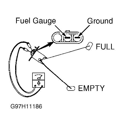
- Remove fuel gauge unit from fuel tank. Measure resistance between fuel gauge unit connector terminals No. 2 and 3 (component side) with fuel gauge unit float at full position and at empty position. See Fig 1. When fuel gauge unit float is at full position, resistance should be 1-5 ohms. When fuel gauge unit float is at empty position, resistance should be 103-117 ohms. Resistance should smoothly change as fuel gauge unit float is moved from full to empty position. If resistances are not as specified, replace fuel gauge unit. Go to step 17. If resistances are as specified, go to next step.
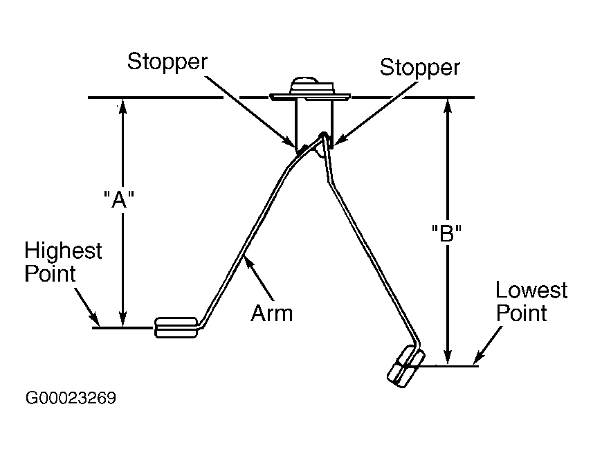
- Measure fuel gauge unit float height as indicated in illustration. See Fig 2. Distance "A" should be 8.42" (214 mm). Distance "B" should be 9.88" (251 mm). If problem exists, adjust fuel gauge unit float arm or replace fuel gauge unit as necessary. Go to step 17. If problem does not exist, go to next step.
- Turn ignition off. Check PCM connector C-90 for loose, damaged or corroded terminals. If problem exists, repair or replace connector. Go to step 17. If problem does not exist, go to next step.
- Check for damage to Black wire between fuel gauge unit and ground. If problem exists, repair Black wire. Go to step 17. If problem does not exist, go to next step.
- Check continuity between fuel gauge unit connector terminal No. 2 and PCM connector C-90 terminal No. 60 (Yellow wire). Continuity should exist. Then, check continuity between ground and fuel gauge unit connector terminal No. 2. Continuity should not exist. If continuity is not as specified, repair open or short circuit to ground in Yellow wire. Go to next step. If continuity is as specified, replace PCM. Go to next step.
- Test drive vehicle following OBD-II drive cycle other monitor pattern. See OTHER MONITOR under OBD-II DRIVE CYCLES under VERIFYING REPAIRS. Check for DTCs. If DTC P0461 is output, go to step 1 and retry test procedure. If DTC P0461 is not output, inspection is complete.
 Courtesy of MITSUBISHI MOTOR SALES OF AMERICA.
 Courtesy of MITSUBISHI MOTOR SALES OF AMERICA.