Installation Procedure
 Courtesy of GENERAL MOTORS CORP.
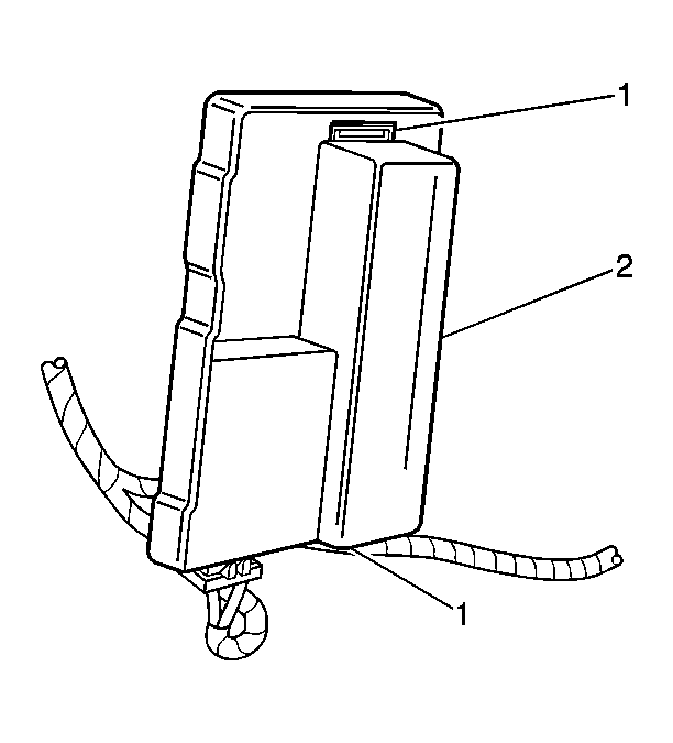
- Slide the ASM control module (2) into the mounting bracket. Engage the two retaining tabs (1) on the mounting bracket.
 Courtesy of GENERAL MOTORS CORP.
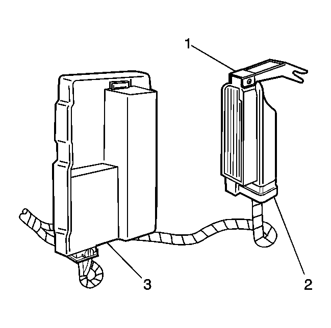
- Connect the accelerator and servo control module (ASM) connector as follows:
- Engage the base of the connector (2) into the ASM control module (3).
- Push the top of the connector (2) into the ASM control module (3).
- Push the locking lever (1) downward. Ensure the lever seats flush with the top of the connector housing.
 Courtesy of GENERAL MOTORS CORP.
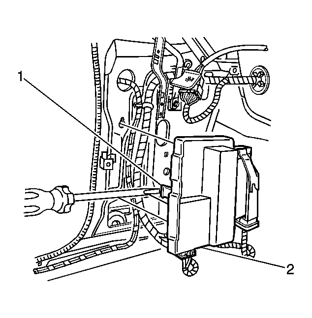
- Engage the upper retaining tab by pushing upward on the bracket.
- Engage the lower retaining tab (1) by gently pushing inward on the base of the mounting bracket (2).
- Install the left hand hinge pillar trim panel. Refer to Trim Replacement - Hinge Pillar
in Interior Trim.
- Connect the battery negative cable. Refer to Battery Negative Cable Disconnect/Connect Procedure
in Engine Electrical.