ABS Description and Operation: Notes
WARNING: This page is about a different car, the 2005 Pontiac Vibe. However, it is still accessible from the selected car via links, so may be relevant.
 Courtesy of GENERAL MOTORS CORP.
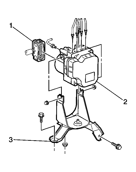
| Callout |
Component Name |
| 1 |
EBCM Wiring Harness Connector |
| 2 |
Brake Pressure Modulator Valve (BPMV)/Electronic Brake Control Module (EBCM) |
| 3 |
EBCM/BPMV Mounting Bracket |
 Courtesy of GENERAL MOTORS CORP.
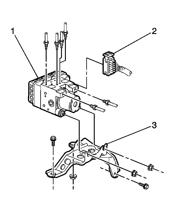
| Callout |
Component Name |
| 1 |
Brake Pressure Modulator Valve (BPMV)/Electronic Brake Control Module (EBCM) |
| 2 |
EBCM Wiring Harness Connector |
| 3 |
EBCM/BPMV Mounting Bracket |
 Courtesy of GENERAL MOTORS CORP.
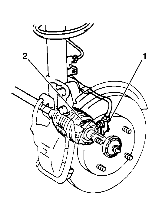
| Callout |
Component Name |
| 1 |
Front Wheel Speed Sensor |
| 2 |
Front Wheel Speed Sensor Ring |
 Courtesy of GENERAL MOTORS CORP.
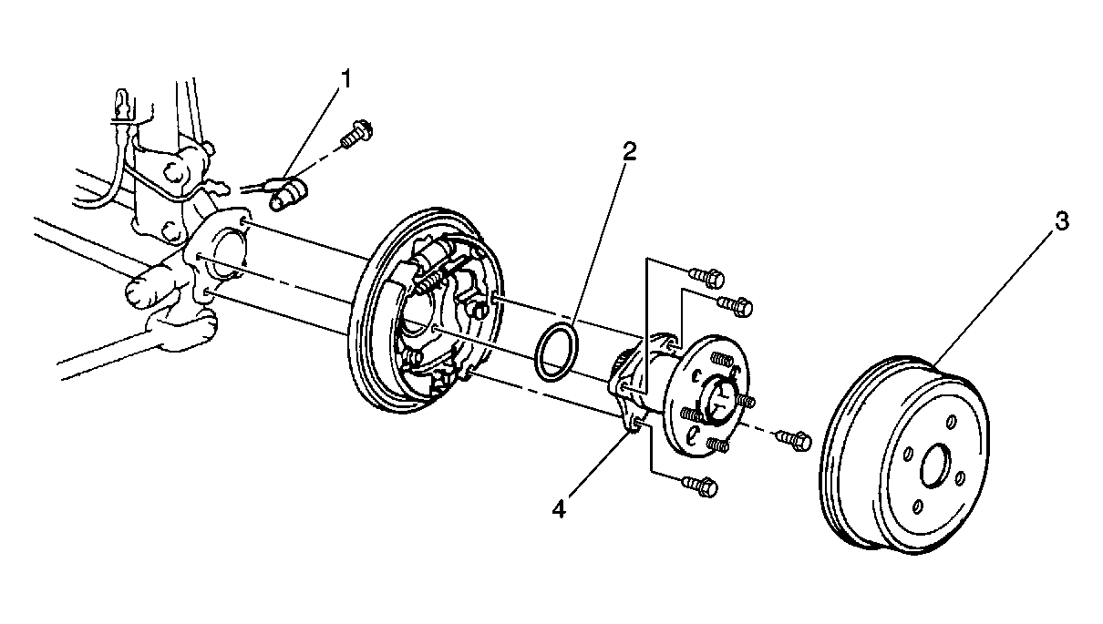
| Callout |
Component Name |
| 1 |
Rear Wheel Speed Sensor |
| 2 |
O-Ring |
| 3 |
Brake Drum |
| 4 |
Rear Hub and Bearing Assembly |
 Courtesy of GENERAL MOTORS CORP.
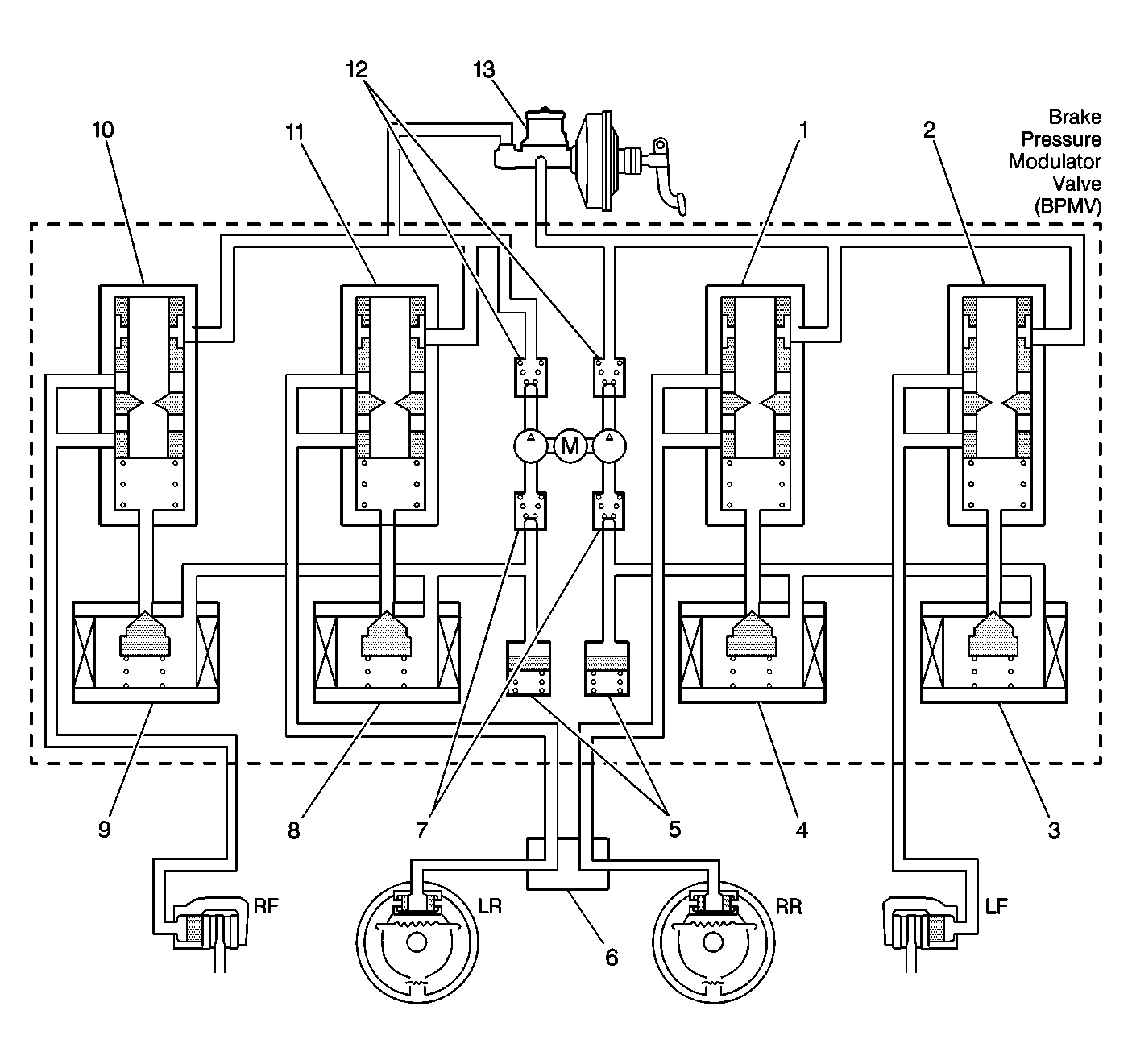
| Callout |
Component Name |
| 1 |
Right Rear Flow Control Valve |
| 2 |
Left Front Flow Control Valve |
| 3 |
Left Front ABS Solenoid Valve |
| 4 |
Right Rear ABS Solenoid Valve |
| 5 |
Buffer Chamber |
| 6 |
Proportioning Valve |
| 7 |
Pump Inlet Check Valves |
| 8 |
Left Rear ABS Solenoid Valve |
| 9 |
Right Front ABS Solenoid Valve |
| 10 |
Right Front Flow Control Valve |
| 11 |
Left Rear Flow Control Valve |
| 12 |
Pump Outlet Check Valves |
| 13 |
Master Cylinder |
 Courtesy of GENERAL MOTORS CORP.
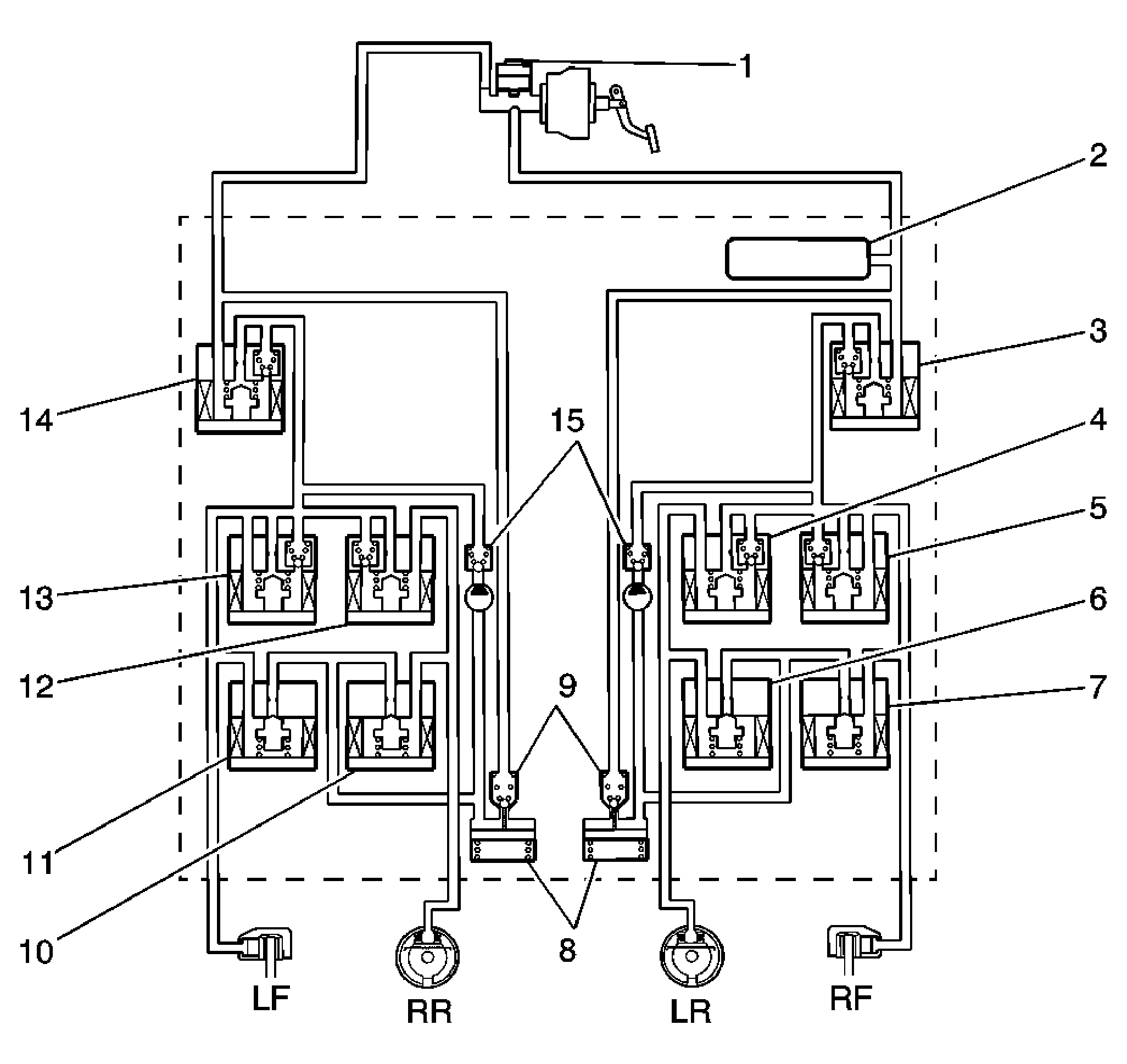
| Callout |
Component Name |
| 1 |
Master Cylinder |
| 2 |
Master Cylinder Pressure Sensor |
| 3 |
Master Cylinder Solenoid Valve |
| 4 |
Left Rear Pressure Hold Valve |
| 5 |
Right Front Pressure Hold Valve |
| 6 |
Left Rear Pressure Reduction Valve |
| 7 |
Right Front Pressure Reduction Valve |
| 8 |
Buffer Chamber |
| 9 |
Pressure Regulator Valves |
| 10 |
Right Rear Pressure Reduction Valve |
| 11 |
Left Front Pressure Reduction Valve |
| 12 |
Right Rear Pressure Hold Valve |
| 13 |
Left Front Pressure Hold Valve |
| 14 |
Master Cylinder Solenoid Valve |
| 15 |
Pump Check Valves |
The vehicle may be equipped with the following braking systems:
- Antilock brake system (ABS)
- Electronic brake force distribution (EBD)
- Traction control system (TCS)
- Vehicle stability enhancement system (VSES) (JL4)
The following components are involved in the operation of the above systems:
- Electronic brake control module (EBCM)-The EBCM controls the system functions and detects failures.
- Brake pressure modulator valve (BPMV)-The BPMV contains the hydraulic valves and pump motor that are controlled electrically by the EBCM. The BPMV uses a 4-circuit configuration with a diagonal split. The BPMV directs fluid from the reservoir of the master cylinder to the left front and right rear wheels and fluid from the other reservoir to the right front and left rear wheels. The diagonal circuits are hydraulically isolated so that a leak or malfunction in one circuit will allow continued braking ability on the other.
IMPORTANT:
There is a rubber isolator located under the BPMV and on the mounting studs. The rubber isolators protect the BPMV and the EBCM from vehicle vibrations.
The BPMV contains the following components:
- Pump motor
- Hold valves, one per wheel
- Reduction Valves, one per wheel
- Master cylinder valves
- Wheel speed sensors (WSS)-As the wheel spins, the wheel speed sensor produces an AC signal. The EBCM uses this AC signal to calculate wheel speed. The wheel speed sensors are replaceable only as part of the wheel hub and bearing assemblies.
- Traction control switch-The traction control system (TCS) is manually disabled or enabled using the traction control switch.
- Deceleration sensor (AWD vehicles)-The EBCM uses the deceleration sensor as an indication of the lateral acceleration/deceleration of the vehicle.
- Yaw rate/deceleration sensor (w/JL4)-The EBCM uses the yaw rate/deceleration sensor as an indication of the yaw rate and lateral acceleration/deceleration of the vehicle.
- Steering angle sensor (w/JL4)-The EBCM uses the steering angle sensor as an indication of the position and rotation of the steering wheel.
- Brake pressure sensor (w/JL4)-The EBCM uses the brake pressure sensor for more accurate control during a VSES event.