Vehicle Speed Sensor: Testing and Inspection
Vehicle Speed Sensor Schematic:
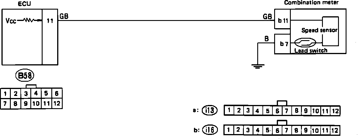
A faulty vehicle speed sensor will set code 33 in the on-board diagnostic system. Refer to the schematic diagram and test the sensor with the diagnostic chart.
VEHICLE SPEED SENSOR DIAGNOSTIC CHART
Vehicle Speed Sensor Diagnostic Chart:
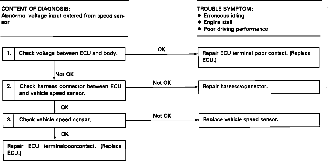
CHECK ECU VOLTAGE
1. Raise and support vehicle with safety stands.
CAUTION: On 4WD models, ensure that all four wheels are off the ground.
2. While driving wheels are slowly turning, measure voltage between ECU connector terminal (B58)11 and ground. It should oscillate between 0V and 5V.
CHECK HARNESS BETWEEN ECU AND SPEED SENSOR
1. Disconnect ECU and combination meter connectors.
2. Measure resistance between ECU and combination meter connectors and ground as follows:
Connector & terminal: Resistance:
(B58)11-(i16)11 0 Ohms
(i16)11-Ground 1M Ohms min.
(i16)7-Ground 0 Ohms
CHECK VEHICLE SPEED SENSOR
Vehicle Speed Sensor Testing:
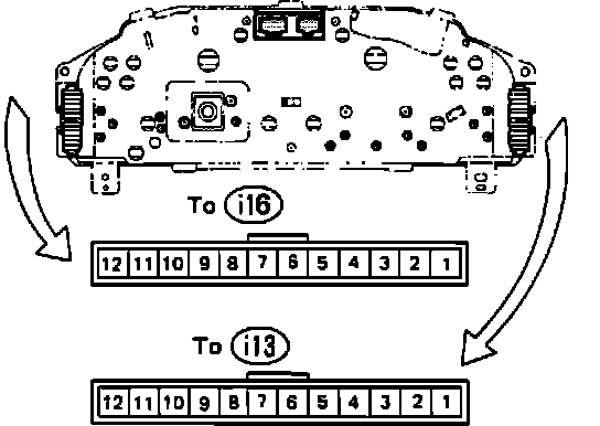
1. Remove combination meter from dash.
2. Disconnect electrical connectors.
3. Insert an appropriate implement (small screwdriver) into hole for speedometer cable and rotate.
4. Check that resistance across meter terminals (i16)11 and (i16)7 deflects between 0 & 1 Mohm four times per revolution.