Electrical Specification
WARNING: This page is about a different car, the 2006 Subaru Baja. However, it is still accessible from the selected car via links, so may be relevant.
 Courtesy of SUBARU OF AMERICA, INC.
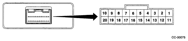
 CRUISE CONTROL MODULE TERMINALS REFERENCE
| Content |
Terminal No. |
Measuring conditions and I/O signals (ignition switch ON and engine idling) |
| Cruise Control Indicator Light |
1 |
- Battery voltage is present when main switch is turned OFF.
- "0" volt is present when main switch is turned ON.
|
| Inhibitor switch (AT) |
4 |
- Battery voltage is present when selector lever is other than "P" or "N" position.
- "0" volt is present when selector lever is set to "P" or "N" position.
|
| Cruise set indicator light |
3 |
- "0" volt is present when cruise control is setted (cruise control is operating).
- Battery voltage is present when cruise control is not setted (cruise control is not operating).
|
| Motor B |
5 |
- ON-and-OFF ("0"-and-battery voltage) operation is alternately repeated while cruise control is operating.
- "0" volt is present when main switch is turned OFF.
|
| Ground |
6 |
- |
| Motor A |
7 |
- ON-and-OFF ("O"-and-battery voltage) operation is alternately repeated while cruise control is operating.
- "0" volt is present when main switch is turned OFF.
|
| RESUME/ACCEL switch |
9 |
- Battery voltage is present when command switch is turned to RESUME/ACCEL position.
- "0" volt is present when command switch is released.
|
| SET/COAST switch |
10 |
- Battery voltage is present when command switch is turned to SET/COAST position.
- "0" volt is present when command switch is released.
|
| Main power supply |
11 |
- Battery voltage is present when main switch is turned ON.
- "0" volt is present when main switch is turned OFF.
|
| Ignition switch |
12 |
- Battery voltage is present when ignition switch is turned ON.
- "0" volt is present when ignition switch is turned OFF.
|
| Motor C |
13 |
- ON-and-OFF ("O"-and-battery voltage) operation is alternately repeated while cruise control is operating.
- "0" volt is present when main switch is turned OFF.
|
| Motor clutch |
14 |
- ON-and-OFF ("O"-and-battery voltage) operation is alternately repeated while cruise control is operating.
- "0" volt is present when vehicle is stopped.
|
| Cruise control main switch |
15 |
- Battery voltage is present during pressing the main switch.
- "0" volt is present when main switch is released.
|
| Brake switch |
16 |
Leave clutch pedal released (MT), while cruise control main switch is turned ON. Then check that;
- Battery voltage is present when brake pedal is released.
- "0" volt is present when brake pedal is depressed.
Additionally only in MT vehicle, keep the cruise control main switch to ON and leave brake pedal released.
Then check that;
- Battery voltage is present when clutch pedal is released.
- "0" volt is present when clutch pedal is depressed.
|
| Data link connector |
17 |
- |
| Data link connector |
18 |
- |
| Vehicle speed sensor (MT) TCM (AT) |
19 |
Lift-up the vehicle until all four wheels are raised off ground, and then rotate any wheel manually.
Approx. "5" and "0" volt pulse signals are alternately input to cruise control module. |
| Stop light switch |
20 |
Turn ignition switch to OFF.
Then check that;
- Battery voltage is present when brake pedal is depressed.
- "0" volt is present when brake pedal is released.
|
|
NOTE:
Voltage at terminals 5, 7, 13 and 14 cannot be checked unless vehicle is driving by cruise control operation.
|