Multi-Function Duct Assembly
- Release the fuel pressure. Ref. to
RELEASING OF FUEL PRESSURE , PROCEDURE, Fuel.
- Disconnect the ground cable from battery.
 Courtesy of SUBARU OF AMERICA, INC.
- Open the fuel filler lid and remove the fuel filler cap.
- Lift up the vehicle.
- Remove the under cover. Ref. to
REMOVAL
, Front Under Cover.
- Drain approximately 3.0 l
(3.2 US qt, 2.6 lmp qt) of engine coolant. Ref. to
DRAINING OF ENGINE COOLANT
, REPLACEMENT, Engine Coolant.
- Lower the vehicle.
- Remove the intake manifold. Ref. to
INTAKE MANIFOLD , REMOVAL, Intake Manifold.
- Remove the bolt, and disconnect the bulkhead harness connector from the engine harness connector and rear engine hanger.
 Courtesy of SUBARU OF AMERICA, INC.
- Slide the engine harness connector in the direction of the arrow and remove it from the rear engine hanger.
 Courtesy of SUBARU OF AMERICA, INC.
- Disconnect the water hose (A) and EGR pipe (B) from the LH side of multi-function duct assembly.
 Courtesy of SUBARU OF AMERICA, INC.
- Disconnect the PCV hose (A) and water hose (B) from the RH side of multi-function duct assembly.
 Courtesy of SUBARU OF AMERICA, INC.
- Disconnect the connectors from the engine coolant temperature sensor (A), oil pressure switch (B) and crankshaft position sensor (C).
 Courtesy of SUBARU OF AMERICA, INC.
- Disconnect the connectors from front oxygen (A/F) sensor (A) and rear oxygen sensor (B).
- Disconnect the connector (C) from the ignition coil of #1 cylinder.
- Disconnect the connectors from oil switching solenoid valve RH (D), oil temperature sensor RH (E) and variable valve lift diagnosis switch (F), and remove the bolt to detach the ground terminal (G).
 Courtesy of SUBARU OF AMERICA, INC.
- Slide the front oxygen (A/F) sensor connector and rear oxygen sensor connector in the direction of the arrow and remove them from the bracket.
 Courtesy of SUBARU OF AMERICA, INC.
- Disconnect the connector from the ignition coil of #4 cylinder.
- Disconnect the connectors from the oil switching solenoid valve LH (A) and camshaft position sensor LH (B).
 Courtesy of SUBARU OF AMERICA, INC.
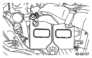
- Remove the PCV pipe, multi-function duct assembly and engine harness as a single unit from the engine.
 Courtesy of SUBARU OF AMERICA, INC.
- Remove the bolts (A) and remove the multifunction duct assembly from the PCV pipe.
- Remove the clips (B) and remove the engine harness from the PCV pipe.
 Courtesy of SUBARU OF AMERICA, INC.