- Release the fuel pressure. Ref. to FUEL INJECTION (FUEL SYSTEMS) (H4DO)>Fuel>PROCEDURE>RELEASING OF FUEL PRESSURE .
- Disconnect the ground terminal from battery sensor. Ref. to NOTE>NOTE>BATTERY
.
- Open the fuel filler lid and remove the fuel filler cap.
NOTE:
This operation is required to release the inner pressure of the fuel tank.
- Drain approximately 3.0 L (3.2 US qt, 2.6 Imp qt) of engine coolant. Ref. to COOLING(H4DO)>Engine Coolant>REPLACEMENT>DRAINING OF ENGINE COOLANT
.
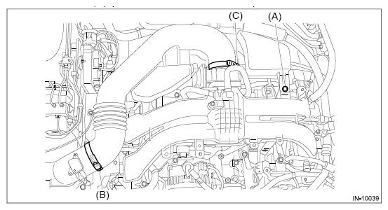
- Remove the clip (A) from the air intake boot.
- Loosen the clamp (B) securing the air cleaner case (rear) to the air intake boot.
- Loosen the clamp (C) which secures the throttle body to the air intake boot.
 Courtesy of SUBARU OF AMERICA, INC.
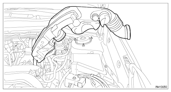
- Remove the air intake boot from the throttle body, and place the air intake boot aside so that it does not interfere with the work.
 Courtesy of SUBARU OF AMERICA, INC.
- Disconnect the preheater hose from throttle body.
 Courtesy of SUBARU OF AMERICA, INC.
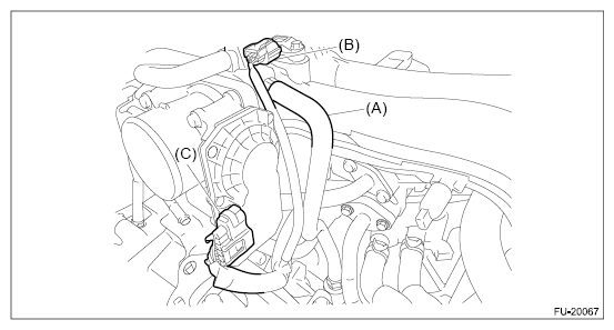
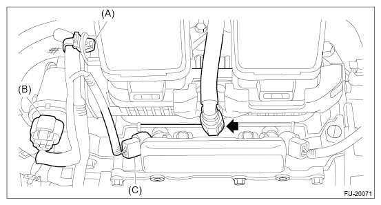
- Disconnect the PCV hose (A) from intake manifold assembly.
- Disconnect the connector (B) from manifold absolute pressure sensor.
- Disconnect the connector (C) from throttle body.
 Courtesy of SUBARU OF AMERICA, INC.
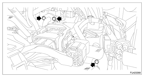
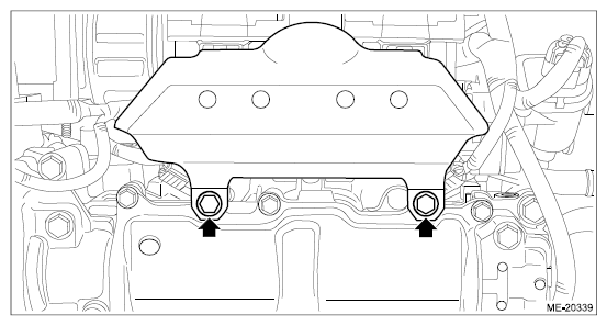
- Remove the bolt securing the EGR cooler to the EGR control valve.
- Loosen the bolts holding the EGR cooler to the cylinder head RH.
 Courtesy of SUBARU OF AMERICA, INC.
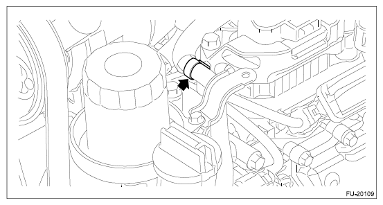
- Disconnect the brake booster vacuum hose from the intake manifold.
 Courtesy of SUBARU OF AMERICA, INC.
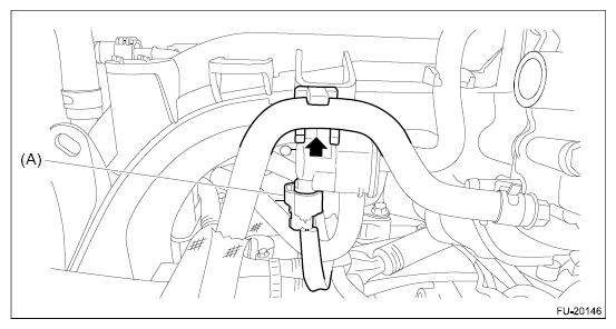
- Disconnect the connector (A) from the purge control solenoid valve.
- Remove the preheater hose from the intake manifold.
 Courtesy of SUBARU OF AMERICA, INC.
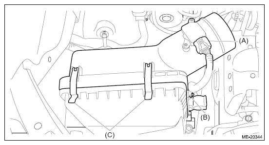
- Disconnect the connector (A) from the mass air flow and intake air temperature sensor, and remove the clip (B) securing the bulkhead wiring harness.
- Remove the clip (C), and the air cleaner case (rear) together with the air cleaner element.
 Courtesy of SUBARU OF AMERICA, INC.
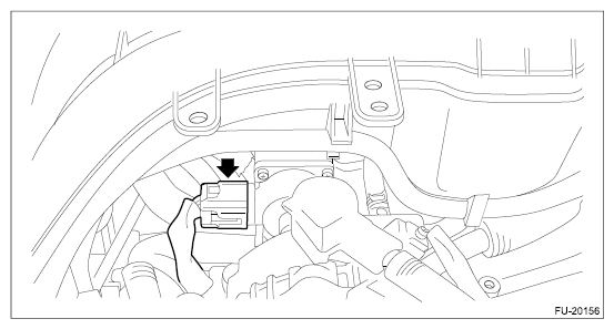
- Disconnect the connector from the EGR control valve.
 Courtesy of SUBARU OF AMERICA, INC.
- Remove the intake manifold protector No. 1 RH.
 Courtesy of SUBARU OF AMERICA, INC.
- Remove the clip (A) securing the engine harness to the intake manifold assembly, and disconnect the connector (B) from the tumble generator valve and disconnect the connector (C) from the fuel injector #3.
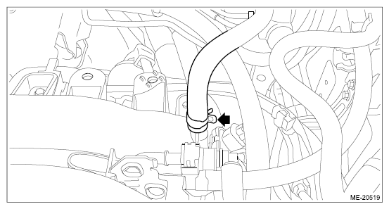
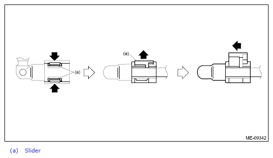
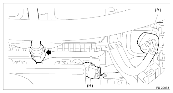
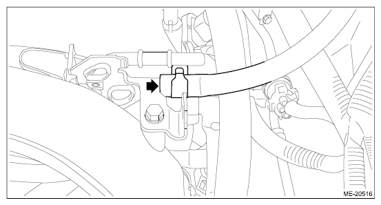
- Disconnect the fuel delivery pipe from the fuel pipe RH.
CAUTION:
- Be careful not to spill fuel.
- Catch the fuel from the pipes using a container or cloth.
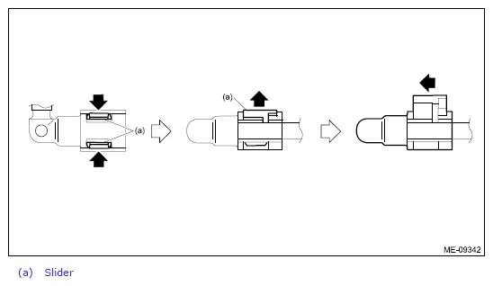
NOTE:
Disconnect the quick connector as shown in the figure.
 Courtesy of SUBARU OF AMERICA, INC.
 Courtesy of SUBARU OF AMERICA, INC.
- Remove the intake manifold protector No. 1 LH.
 Courtesy of SUBARU OF AMERICA, INC.
- Remove the clip which secures the engine harness to the intake manifold protector No. 3.
 Courtesy of SUBARU OF AMERICA, INC.
- Disconnect the connector (A) from the tumble generator valve, and disconnect the connector (B) from the fuel injector #4.
- Disconnect the fuel delivery pipe from the fuel pipe LH.
CAUTION:
- Be careful not to spill fuel.
- Catch the fuel from the pipes using a container or cloth.
NOTE:
Disconnect the quick connector as shown in the figure.
 Courtesy of SUBARU OF AMERICA, INC.
 Courtesy of SUBARU OF AMERICA, INC.
- Disconnect the fuel delivery tube and evaporation hose.
CAUTION:
- Be careful not to spill fuel.
- Catch the fuel from the tubes using a container or cloth.
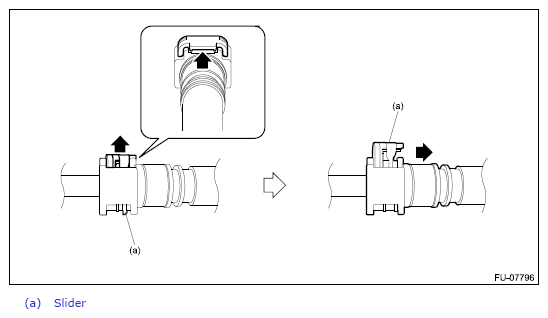
- Disconnect the quick connector on the fuel delivery tube from the fuel pipe assembly, and remove the clip (A) securing the fuel delivery tube.
NOTE:
Disconnect the quick connector as shown in the figure.
 Courtesy of SUBARU OF AMERICA, INC.
 Courtesy of SUBARU OF AMERICA, INC.
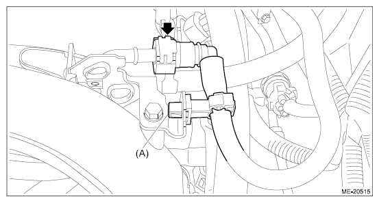
- Disconnect the evaporation hose from the fuel pipe assembly.
 Courtesy of SUBARU OF AMERICA, INC.
- Remove the intake manifold assembly from the cylinder head together with the intake manifold protector No. 2 and the intake manifold protector No. 3.