DTC P0606 Control Module Processor: Notes
DTC DETECTING CONDITION:
Immediately at fault recognition
TROUBLE SYMPTOM:
- Improper idling
- Poor driving performance
CAUTION:
After servicing or replacing faulty parts, perform Clear Memory Mode <Ref. to
OPERATION
, Clear Memory Mode.>, and Inspection Mode <Ref. to
PROCEDURE
, Inspection Mode.>.
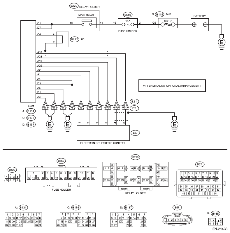
WIRING DIAGRAM:
Engine Electrical System <Ref. to
WIRING DIAGRAM
, Engine Electrical System.>
 Courtesy of SUBARU OF AMERICA, INC.
| Step |
Check |
Yes |
No |
1 CHECK INPUT VOLTAGE OF ECM.
- Turn the ignition switch to ON.
- Measure the voltage between ECM connector and chassis ground.
Connector & terminal
(B136) No. 1 (+) - Chassis ground (-):
(B137) No. 7 (+) - Chassis ground (-):
|
Is the voltage 10 - 13 V? |
Go to step 2. |
Repair the open or short to ground in the power supply circuit. |
2 CHECK INPUT VOLTAGE OF ECM.
- Start the engine.
- Measure the voltage between ECM connector and chassis ground.
Connector & terminal
(B136) No. 1 (+) - Chassis ground (-):
(B137) No. 7 (+) - Chassis ground (-):
|
Is the voltage 13 - 15 V? |
Go to step 3. |
Repair the open or short to ground in the power supply circuit. |
3 CHECK HARNESS BETWEEN ECM AND ELECTRONIC THROTTLE CONTROL CONNECTOR.
- Turn the ignition switch to OFF.
- Disconnect the connector from ECM.
- Disconnect the connectors from electronic throttle control.
- Measure the resistance of harness between ECM connector and electronic throttle control connector.
Connector & terminal
(B134) No. 19 - (E57) No. 5:
(B134) No. 29 - (E57) No. 3:
|
Is the resistance less than 1 Ω? |
Go to step 4. |
Repair the harness and connector.
NOTE:
In this case, repair the following item:
- Open circuit in harness between ECM connector and electronic throttle control connector
- Poor contact of coupling connector
|
4 CHECK ECM GROUND HARNESS.
- Connect all connectors.
- Turn the ignition switch to ON.
- Measure the voltage between ECM connector and chassis ground.
Connector & terminal
(B134) No. 3 (+) - Chassis ground (-):
(B134) No. 4 (+) - Chassis ground (-):
(B134) No. 6 (+) - Chassis ground (-):
(B137) No. 1 (+) - Chassis ground (-):
(B137) No. 3 (+) - Chassis ground (-):
|
Is the voltage less than 1 V? |
Check the connector for poor contact and check the harness.
Replace the ECM if no fault is found. <Ref. to
Engine Control Module (ECM)
.> |
Repair the harness and connector.
NOTE:
In this case, repair the following item:
- Open circuit in ground circuit
- Further tightening of the engine ground terminal
- Poor contact of ECM connector
- Poor contact of coupling connector
|