September 30: LEMON manuals is back up on a temporary server! Slowness is possible
Throttle Position (TP) Sensor
- Disconnect negative battery cable and TP sensor connector. See Fig 1
. Using ohmmeter, check resistance between indicated terminals. See THROTTLE POSITION (TP) SENSOR RESISTANCE
table.
- If resistance is not as specified, adjust the TP sensor. See the ADJUSTMENTS
article. If resistance is not as specified after adjustment, replace TP sensor. For further diagnostic procedures, see the TESTS W/CODES
article.
THROTTLE POSITION (TP) SENSOR RESISTANCE
| Application |
Ohms |
| Between Terminals "A" & "C" |
100-100,000 |
| Between Terminals "A" & "D" |
2870-5330 |
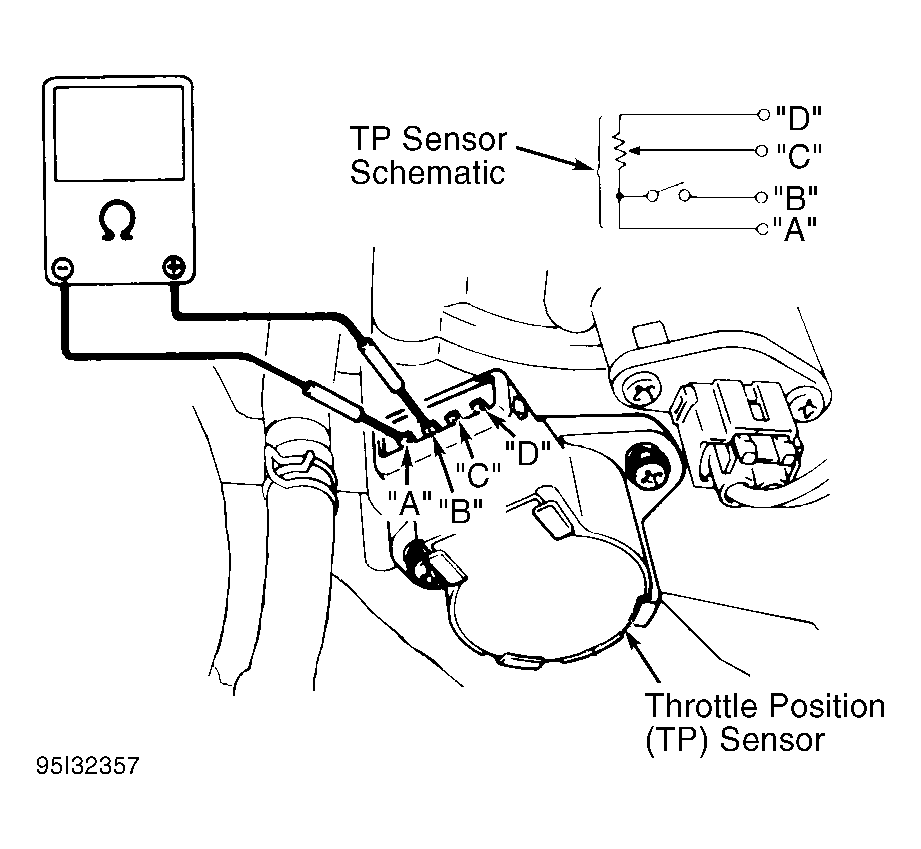 Courtesy of SUZUKI OF AMERICA CORP.
- Disconnect negative battery cable. Remove instrument cluster. Connect ohmmeter between RSW and GND terminals on back of instrument cluster. Insert screwdriver into speedometer cable connector. Rotate screwdriver. See Fig 2
.
- Ohmmeter reading should alternate between zero and infinity 4 times for each revolution of speedometer cable. Replace speedometer if VSS does not test as described.
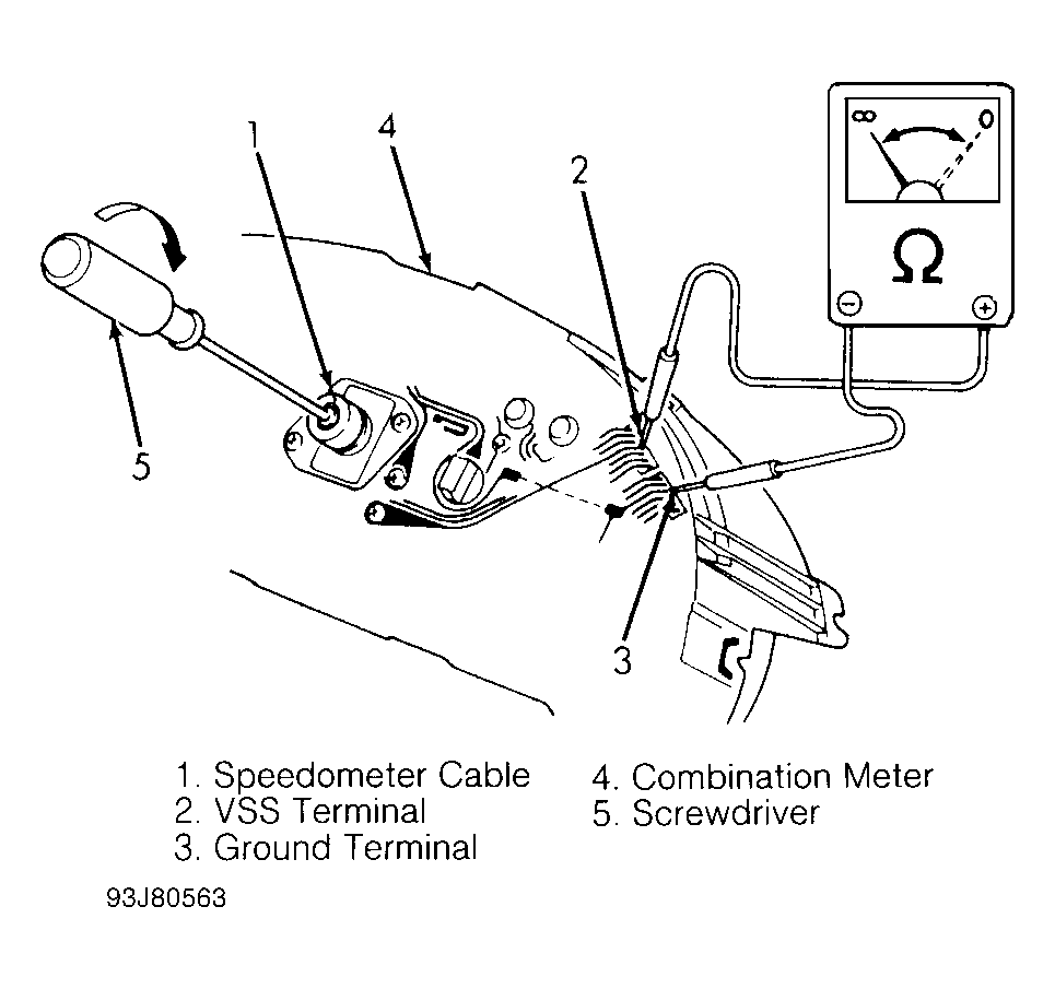 Courtesy of SUZUKI OF AMERICA CORP.