How to Read Connector Layout Diagram
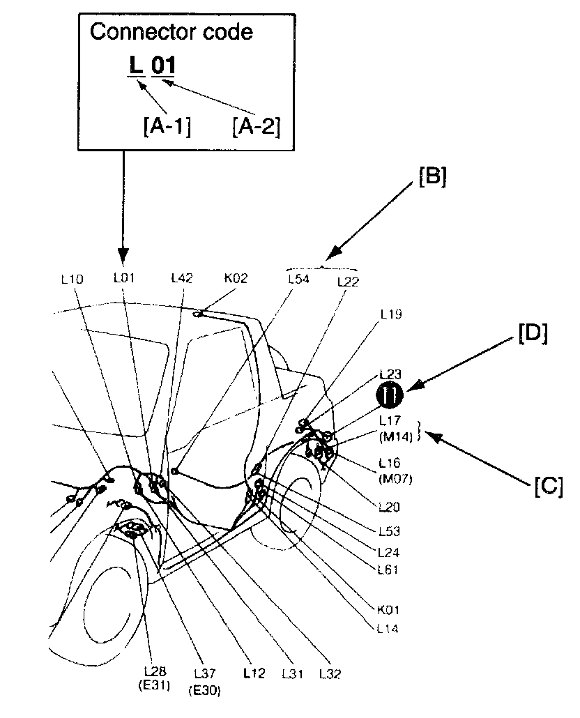
When necessary to know the location of an electrical part or intermediate connector, it is easily possible to retrieve it by this diagram.
First consult ("SYSTEM CIRCUIT DIAGRAM") or connector table for the connector code of interest. Second refer to the diagrams and look for the same code. More information on use of the code is illustrated below.
[A-1]:
Harness symbol and corresponding harness name
A: Battery cable
B: A/C harness
C: Engine harness
D: Injector harness
E: Main harness
Oil pressure wire
Console wire
G: Instrument panel harness
J: Front and rear door harness
K: Roof wire
Spot light wire
L: Floor harness
O: Back door harness License light wire
High mounted stop light wire
Q: Air bag harness
R: Fuel pump harness
[A-2]:
Connector Number (Serial number: 01)
[B]:
This indicates the intermediate connector.
Nos. are given to male and female connectors respectively. When the harness symbol (alphabet) is different, so is the harness name. (For the details, refer to [A-1] above.)
[C]:
This indicates the connector code.
The connector code in the parentheses () has the same meaning as the above intermediate connector and at the same time, it indicates that there is a harness continuity ("CONNECTOR LAYOUT DIAGRAM"). That is, it suggests that the harness is continued to the other illustration and the continued harness can be identified by the same connector code.
[D]:
This indicates the ground point No.
The same No. is used as the ground point. (For the details, refer to ("GROUND POINT").)