How to Read Connector Codes and Terminal Nos.
How to Read Connector Codes and Terminal Nos.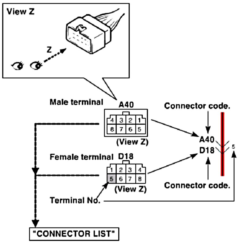
1. Connector code/Terminal No./Terminal layout
- The connector shape and terminal layout are those when viewed from "Z" in the illustration.
Refer to List of Connectors.
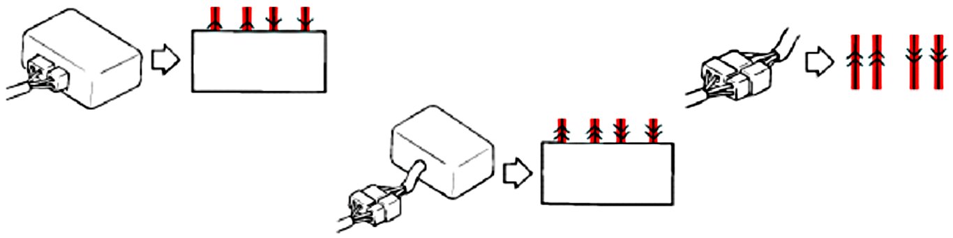
2. Connector type
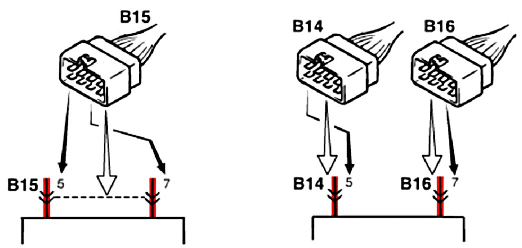
3. Terminals in one connector (Broken line) (B15)/Terminals in different connectors (B14, B16)
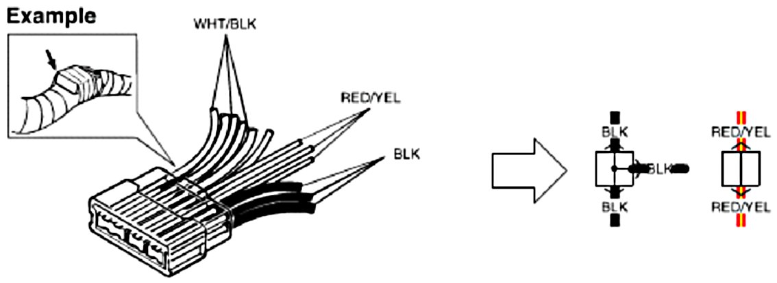
4. Joint connector (J/C)
- The joint connector (J/C) connects several different wires with the same wire color at one place instead of connecting them by welding or caulking one by one. It is not an ordinary connector but a part of the continuous wire in the harness.
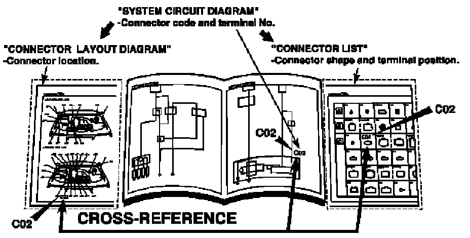
5. Connector location, shape and terminal No.
Refer to Connector Layout Diagram.
Refer to System Circuit Diagram.
Refer to List of Connectors.