Inspection of TCM and Its Circuits
Inspection of TCM and Its Circuits
TCM and its circuits can be checked at TCM wiring connectors by measuring voltage, pulse signal and resistance.
NOTE:
If you connect a voltmeter or an ohmmeter directly to the TCM terminals by removing the TCM connectors, you can damage the TCM.
Never connect a voltmeter or an ohmmeter directly to any terminal on the TCM by disconnecting the TCM connectors.
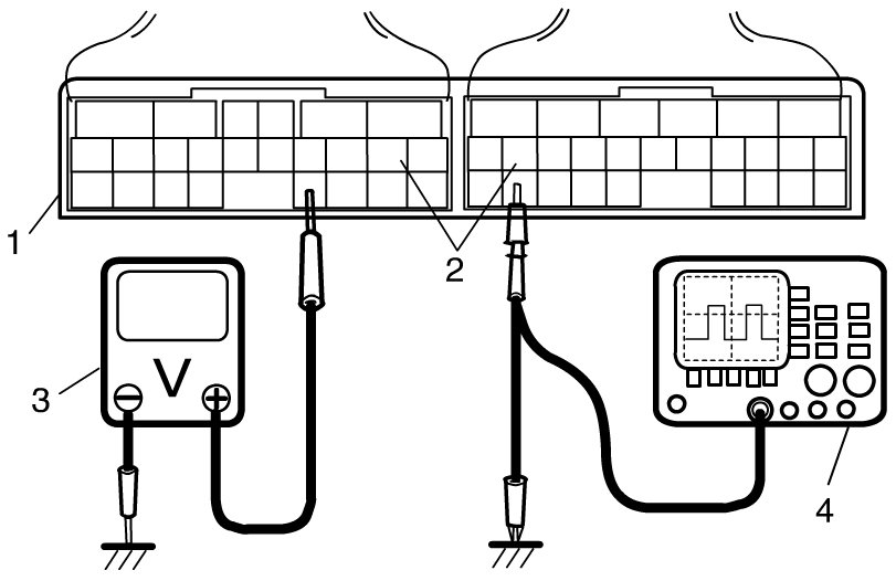
1) Remove TCM (1) from vehicle referring to Service and Repair Transmission Control Module (TCM) Removal and Installation.
2) Connect TCM connectors (2) to TCM.
3) Check voltage and/or pulse signal at each terminal of connectors connected using voltmeter (3) and oscilloscope (4).
NOTE:
- As each terminal voltage is affected by battery voltage, confirm that it is 11 V or more when ignition switch is ON.
- Voltage with asterisk (*) cannot be measured by voltmeter because it is pulse signal. Check it with oscilloscope.
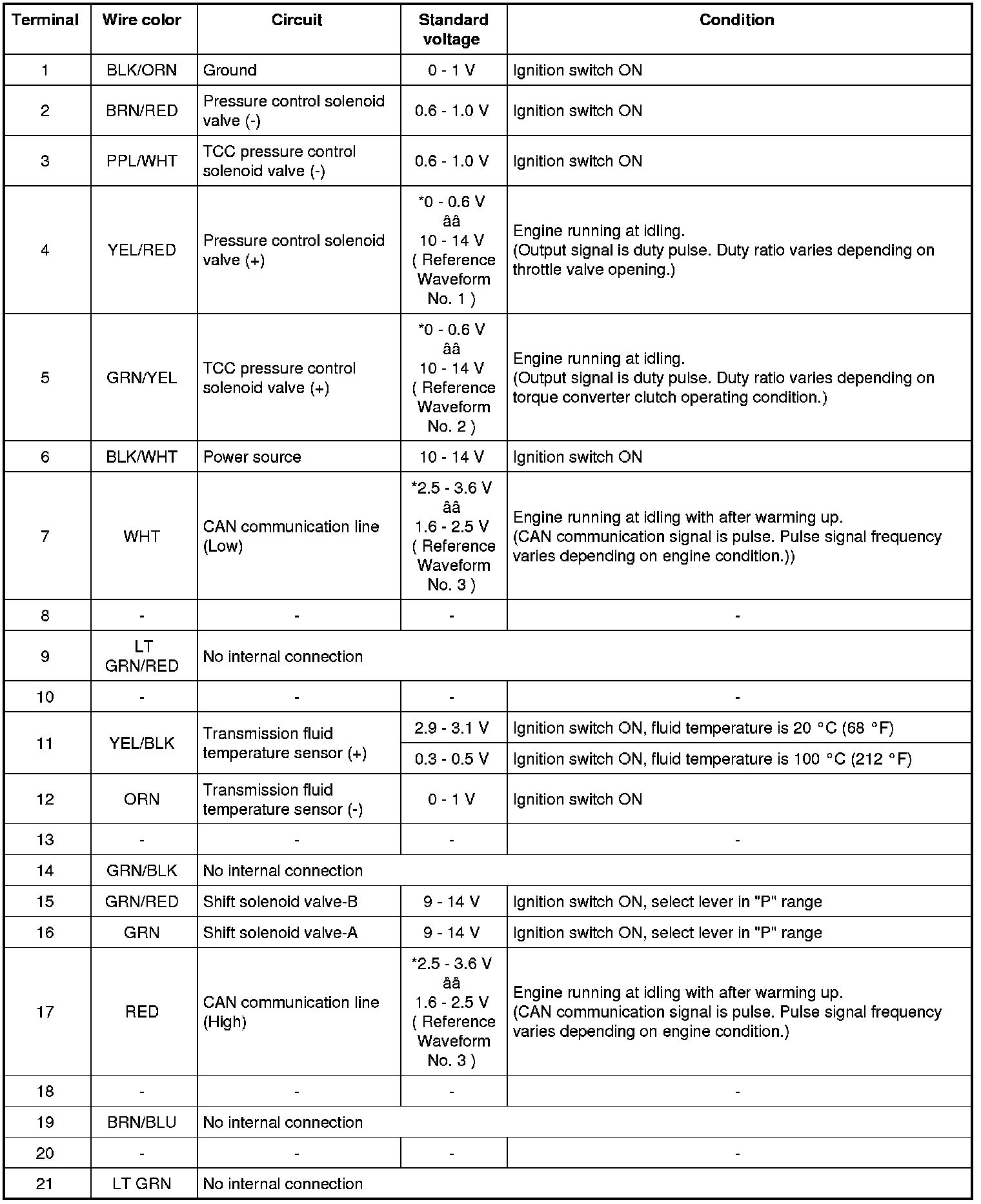
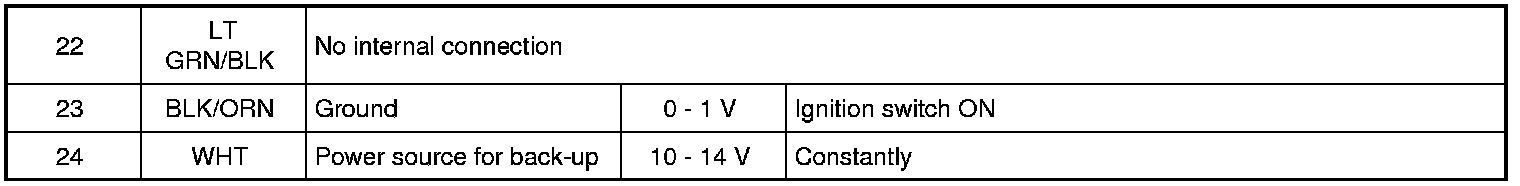
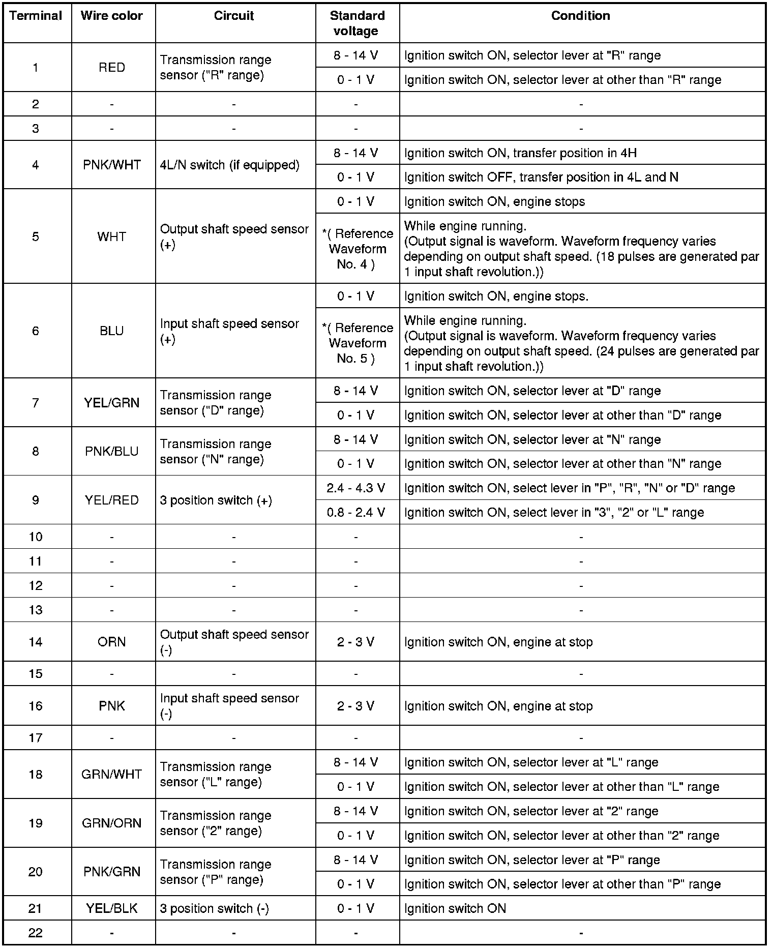
Terminal arrangement of TCM connector (Viewed from harness side)
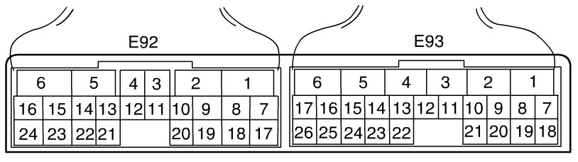
Connector "E92"
Connector "E93"
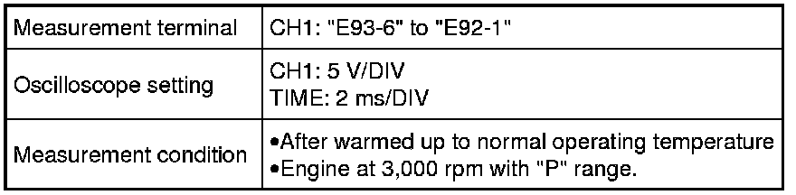
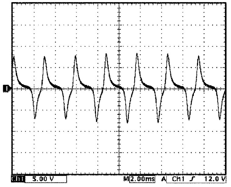
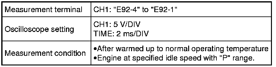
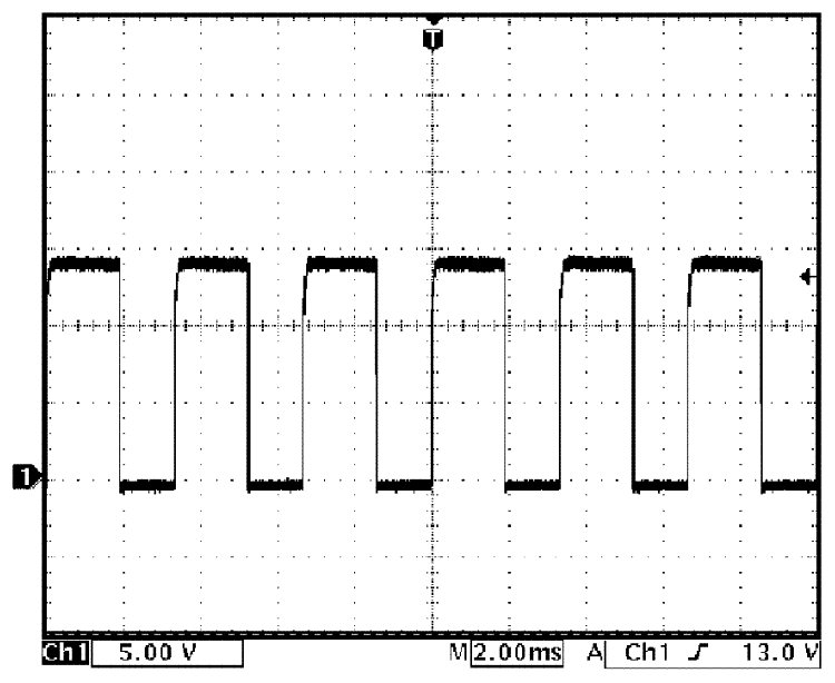
Reference Waveform No. 1
Pressure control solenoid valve signal at engine idling.
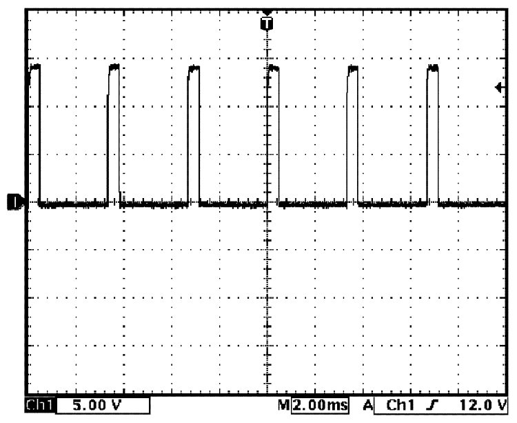
Reference Waveform No. 2
TCC pressure control solenoid valve signal at engine idling.

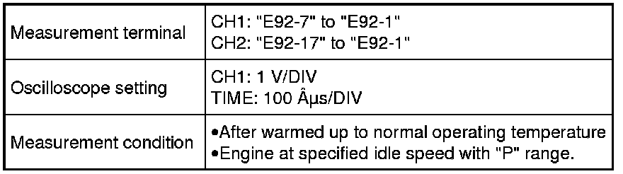
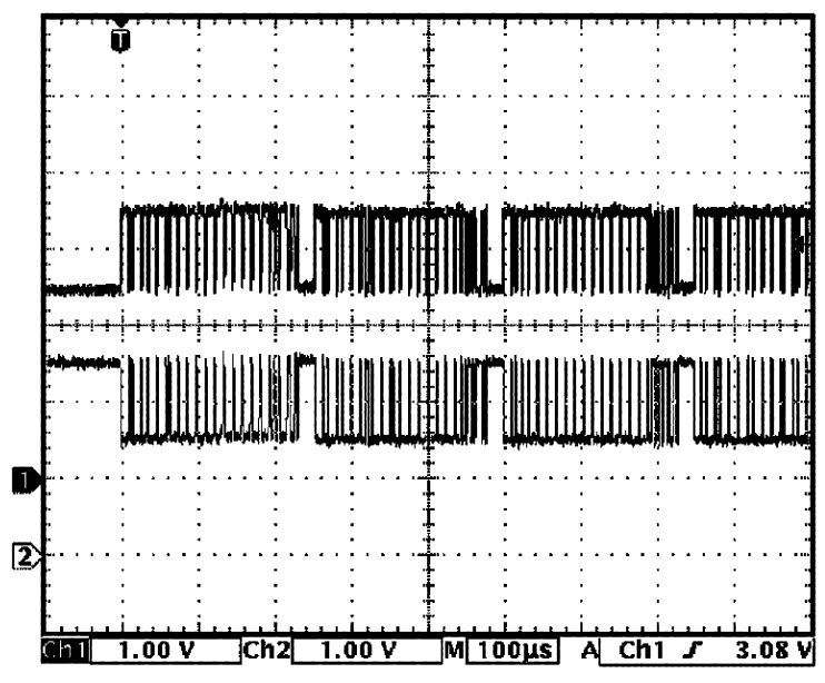
Reference Waveform No. 3
CAN communication line (High & Low) signal at engine idling.
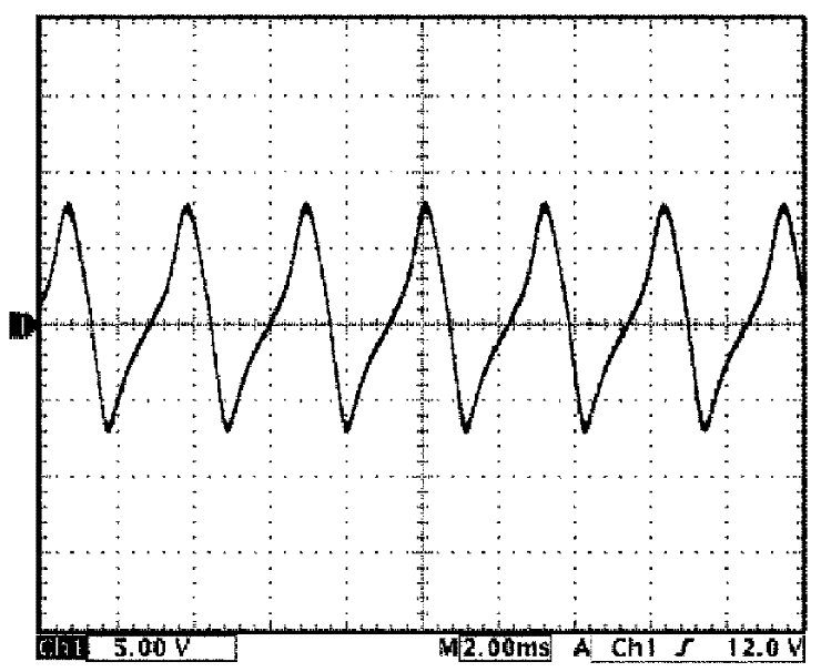
Reference Waveform No. 4
Output shaft speed sensor signal at vehicle speed 40 km/h (25 mile/h).

Reference Waveform No. 5
Input shaft speed sensor signal at engine speed 3000 rpm.