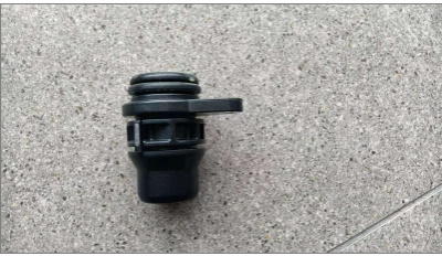
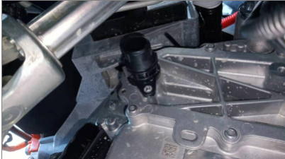
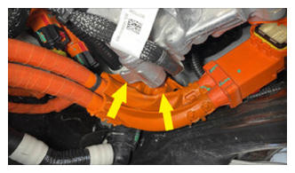
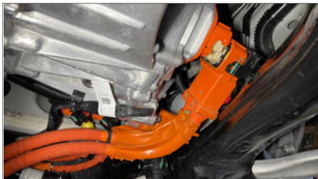
- Install new straight fluid coupling onto the front drive inverter
 Courtesy of TESLA, INC. Courtesy of TESLA, INC.
|
 Courtesy of TESLA, INC. Courtesy of TESLA, INC.
|
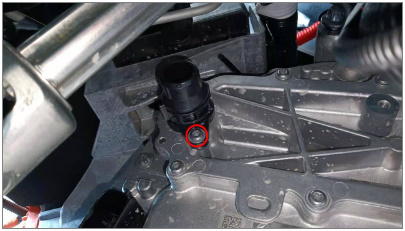
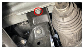
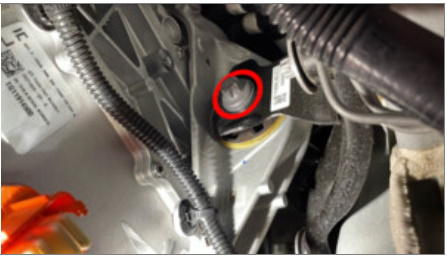
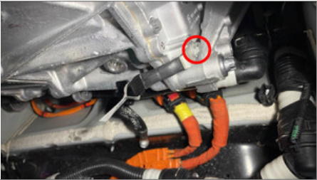
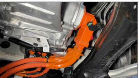
- Install the fastener securing the Straight fluid coupling to the front drive inverter
NOTE:
1x screw, T25, 6 N.m
 Courtesy of TESLA, INC. Courtesy of TESLA, INC.
|
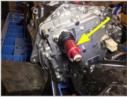
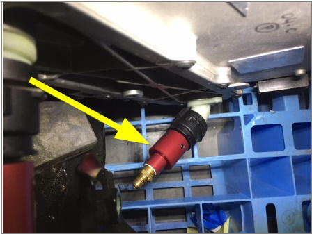
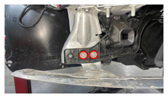
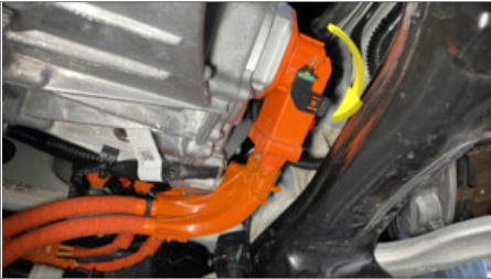
- Install coolant pressure test plug adapter to Straight Fluid Coupling
NOTE:
1x spring clip, Make sure the locking clip is fully seated
 Courtesy of TESLA, INC. Courtesy of TESLA, INC.
|
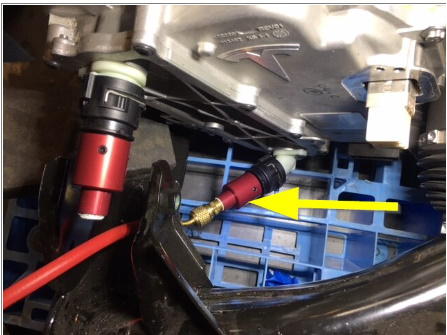
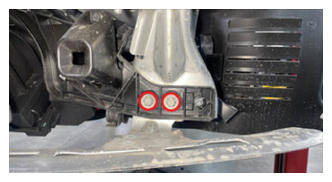
- Install coolant pressure adapter to 55 deg Fluid Coupling
NOTE:
1x spring clip, Make sure the locking clip is fully seated
 Courtesy of TESLA, INC. Courtesy of TESLA, INC.
|
- Attach coolant pressure tester to pressure fitting adapter.
 Courtesy of TESLA, INC. Courtesy of TESLA, INC.
|
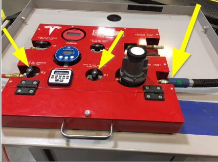
- Attach coolant pressure tester to compressed air line.
NOTE:
Make sure valves are closed on pressure regulator
 Courtesy of TESLA, INC. Courtesy of TESLA, INC.
|
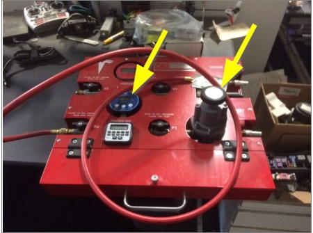
- Set pressure regulator to specified pressure value
NOTE:
Set pressure to 50 psi
 Courtesy of TESLA, INC. Courtesy of TESLA, INC.
|
- Slowly open valve on pressure regulator and allow pressure to reach specification
 Courtesy of TESLA, INC. Courtesy of TESLA, INC.
|
- Close the valve and let the pressure test settle.
NOTE:
Wait 16 seconds for pressure to settle, Record the reading
 Courtesy of TESLA, INC. Courtesy of TESLA, INC.
|
- Perform the coolant pressure leak test
NOTE:
Wait for another 12 seconds and record the reading, Max delta 0.10 psi, Check coolant hose to see if it is fully seated or not if pressure test fails
- Disconnect compressed air from coolant pressure tester
 Courtesy of TESLA, INC. Courtesy of TESLA, INC.
|
- Remove pressure fitting adapter from coolant pressure tester
Courtesy of TESLA, INC.
|
- Remove coolant pressure tester from 55 deg Fluid Coupling.
NOTE:
1x spring clip
Courtesy of TESLA, INC.
|
- Remove coolant pressure test plug adapter from Straight Fluid Coupling.
NOTE:
1x spring clip
Courtesy of TESLA, INC.
|
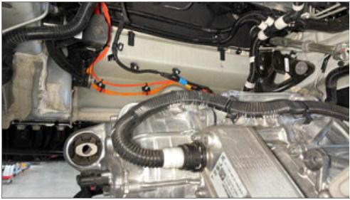
- Connect the inverter to heat exchanger tube to the 90 deg Fluid Coupling
NOTE:
1x spring clip, Perform push-pull-push test to make sure hose is fully seated
 Courtesy of TESLA, INC. Courtesy of TESLA, INC.
|
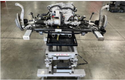
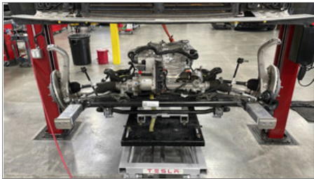
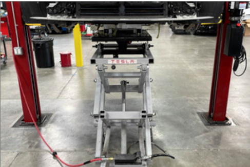
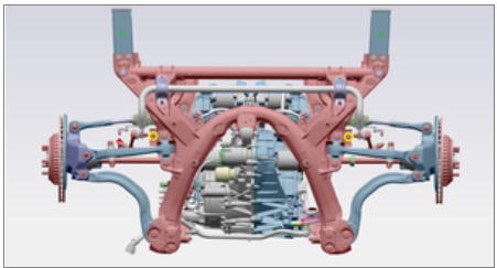
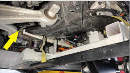
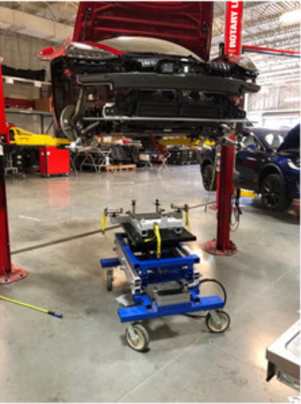
- Position lifting tool and subframe under vehicle for installation
 Courtesy of TESLA, INC. Courtesy of TESLA, INC.
|
 Courtesy of TESLA, INC. Courtesy of TESLA, INC.
|
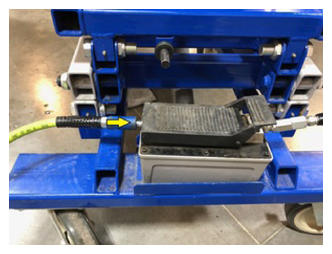
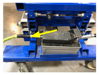
- Connect air supply to subframe lifting tool
 Courtesy of TESLA, INC. Courtesy of TESLA, INC.
|
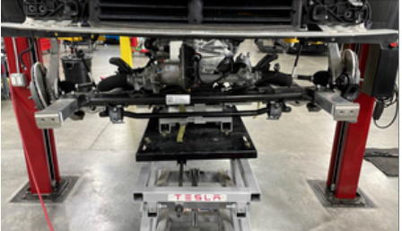
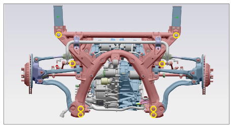
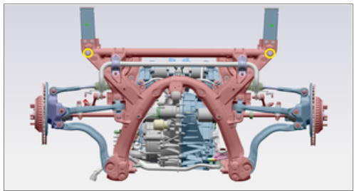
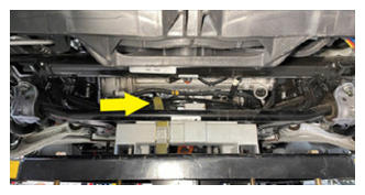
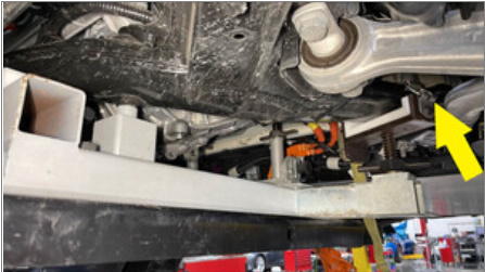
- Raise front subframe assembly onto vehicle
NOTE:
Raise front subframe assembly and line up into vehicle, Guide the motor mount bushings into the mount isolators, Verify the front struts are also positioned correctly over the front axles
Courtesy of TESLA, INC.
|
 Courtesy of TESLA, INC. Courtesy of TESLA, INC.
|
 Courtesy of TESLA, INC. Courtesy of TESLA, INC.
|
 Courtesy of TESLA, INC. Courtesy of TESLA, INC.
|
 Courtesy of TESLA, INC. Courtesy of TESLA, INC.
|
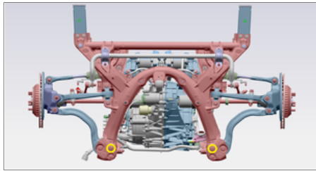
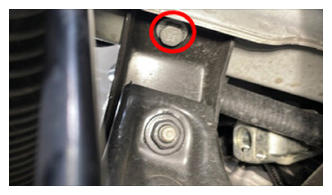
- Thread in all bolts securing front subframe to body.
NOTE:
2x bolts, 21mm, 125 N.m, 2x bolts, 15mm, 50 N.m, 2x bolts, 18mm, 72 N.m, 2x bolts, 15mm, 50 N.m, Line up and start threads for all fasteners, Install new fasteners, Torque at later step
 Courtesy of TESLA, INC. Courtesy of TESLA, INC.
|
- Loosely install the bolts securing front end carrier to RH front subframe crash can assembly
NOTE:
2x bolts, 13mm, 16 N.m
 Courtesy of TESLA, INC. Courtesy of TESLA, INC.
|
- Loosely install the bolts securing front end carrier to LH front subframe crash can assembly
NOTE:
2x bolts, 13mm, 16 N.m
 Courtesy of TESLA, INC. Courtesy of TESLA, INC.
|
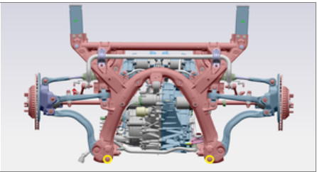
- Torque larger bolts securing the rear portion of the front subframe to body
NOTE:
2x bolts, 21mm, 125 N.m
 Courtesy of TESLA, INC. Courtesy of TESLA, INC.
|
 Courtesy of TESLA, INC. Courtesy of TESLA, INC.
|
 Courtesy of TESLA, INC. Courtesy of TESLA, INC.
|
- Torque smaller bolts securing the rear portion of the front subframe to body
NOTE:
2x bolts, 15mm, 50 N.m
 Courtesy of TESLA, INC. Courtesy of TESLA, INC.
|
 Courtesy of TESLA, INC. Courtesy of TESLA, INC.
|
 Courtesy of TESLA, INC. Courtesy of TESLA, INC.
|
- Torque bolts securing the front portion of the front subframe to body.
NOTE:
2x bolts, 18mm, 72 N.m
 Courtesy of TESLA, INC. Courtesy of TESLA, INC.
|
 Courtesy of TESLA, INC. Courtesy of TESLA, INC.
|
 Courtesy of TESLA, INC. Courtesy of TESLA, INC.
|
- Torque bolts securing front subframe mid mounts to body.
NOTE:
2x bolts, 15mm, 50 N.m
 Courtesy of TESLA, INC. Courtesy of TESLA, INC.
|
 Courtesy of TESLA, INC. Courtesy of TESLA, INC.
|
 Courtesy of TESLA, INC. Courtesy of TESLA, INC.
|
- Torque the bolts securing front end carrier to RH front subframe crash can assembly.
NOTE:
2x bolts, 13mm, 16 N.m
Courtesy of TESLA, INC.
|
- Torque the bolts securing front end carrier to LH front subframe crash can assembly
NOTE:
2x bolts, 13mm, 16 N.m
Courtesy of TESLA, INC.
|
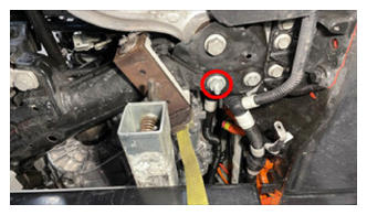
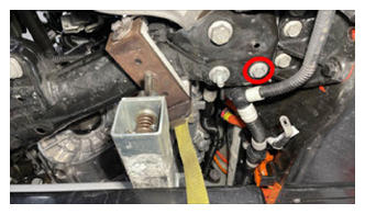
- Install bolt securing the RH motor mount to the RH motor mount bracket
NOTE:
1x bolt, E18, 105 N.m, May need adjust subfame jig to align mount with bolt hole
 Courtesy of TESLA, INC. Courtesy of TESLA, INC.
|
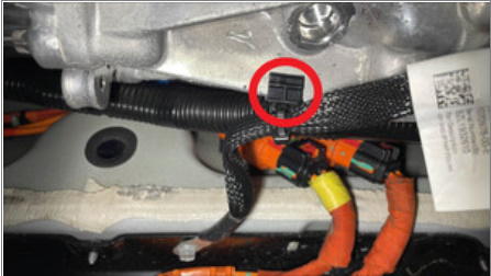
- Secure FDU resolver connection
NOTE:
1x locking connector, Secure connection and fully engage locking tab
 Courtesy of TESLA, INC. Courtesy of TESLA, INC.
|
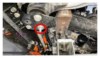
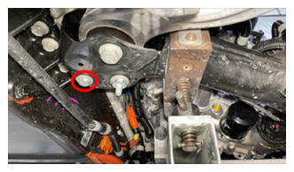
- Install bolt securing the LH motor mount to the LH motor mount bracket
NOTE:
1x bolt, E18, 105 N.m, May need adjust subfame jig to align mount with bolt hole
 Courtesy of TESLA, INC. Courtesy of TESLA, INC.
|
- Release fixture straps from front subframe
 Courtesy of TESLA, INC. Courtesy of TESLA, INC.
|
 Courtesy of TESLA, INC. Courtesy of TESLA, INC.
|
 Courtesy of TESLA, INC. Courtesy of TESLA, INC.
|
- Lower the subframe lifting tool from the vehicle
NOTE:
Unlatch the subframe lifting tool from front subframe
 Courtesy of TESLA, INC. Courtesy of TESLA, INC.
|
- Disconnect air supply from subframe lifting tool
 Courtesy of TESLA, INC. Courtesy of TESLA, INC.
|
- Remove the subframe lifting tool from vehicle
Courtesy of TESLA, INC.
|
- Place FDU ground strap to original position and torque bolt to HV battery
NOTE:
1x bolt, 10mm, 10 N.m
 Courtesy of TESLA, INC. Courtesy of TESLA, INC.
|
 Courtesy of TESLA, INC. Courtesy of TESLA, INC.
|
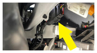
- Install FDU ground strap harness clip to FDU
NOTE:
1x clip, Make sure to properly route the ground strap
 Courtesy of TESLA, INC. Courtesy of TESLA, INC.
|
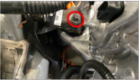
- Install bolt securing FDU ground strap to FDU
NOTE:
1x bolt, 10mm, 6 N.m
 Courtesy of TESLA, INC. Courtesy of TESLA, INC.
|
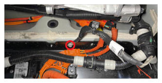
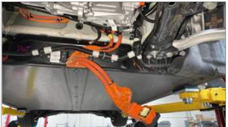
- Position FDU HV harness to casting for installation
 Courtesy of TESLA, INC. Courtesy of TESLA, INC.
|
 Courtesy of TESLA, INC. Courtesy of TESLA, INC.
|
 Courtesy of TESLA, INC. Courtesy of TESLA, INC.
|
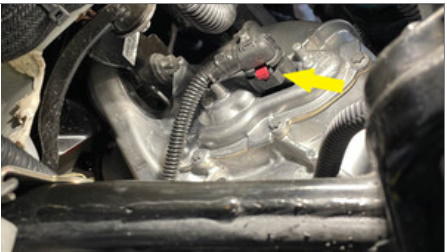
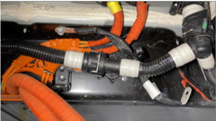
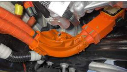
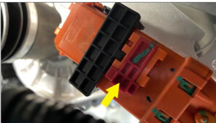
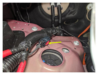
- Secure FDU HV harness connection to FDU
NOTE:
1x locking connector, Verify lever is in the upright and open position, Carefully seat connector and allow lever to engage, Fully secure lever and engage red locking tab, Do not damage connetcor or header
 Courtesy of TESLA, INC. Courtesy of TESLA, INC.
|
 Courtesy of TESLA, INC. Courtesy of TESLA, INC.
|
 Courtesy of TESLA, INC. Courtesy of TESLA, INC.
|
 Courtesy of TESLA, INC. Courtesy of TESLA, INC.
|
- Install bolt securing FDU HV harness to FDU
NOTE:
1x bolt, 10mm, 10 N.m
 Courtesy of TESLA, INC. Courtesy of TESLA, INC.
|
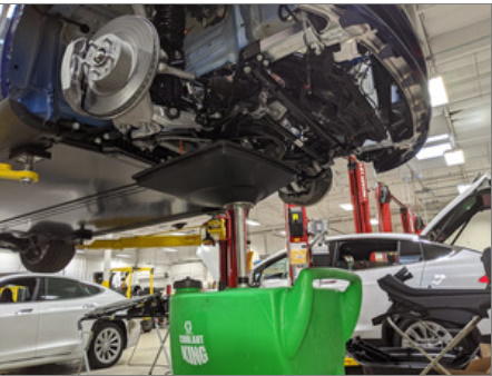
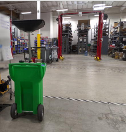
- Position coolant drain container under RH side of vehicle
NOTE:
Position to catch all coolant loss
 Courtesy of TESLA, INC. Courtesy of TESLA, INC.
|
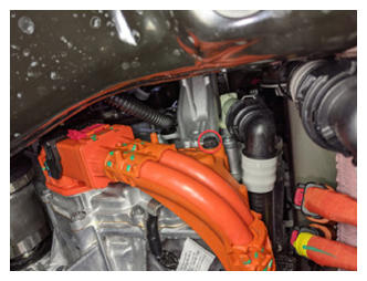
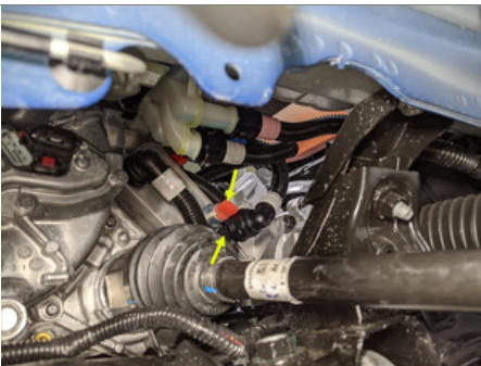
- Remove plugs and connect FDU coolant inlet hose at the RH side of vehicle
NOTE:
1x spring clip
 Courtesy of TESLA, INC. Courtesy of TESLA, INC.
|
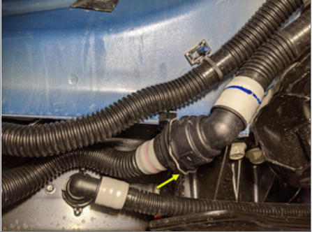
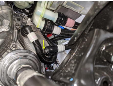
- Remove plugs and connect coolant hose from coolant bottle to oil cooler
NOTE:
1x spring clip
 Courtesy of TESLA, INC. Courtesy of TESLA, INC.
|
 Courtesy of TESLA, INC. Courtesy of TESLA, INC.
|
- Remove coolant drain container from underneath vehicle
 Courtesy of TESLA, INC. Courtesy of TESLA, INC.
|
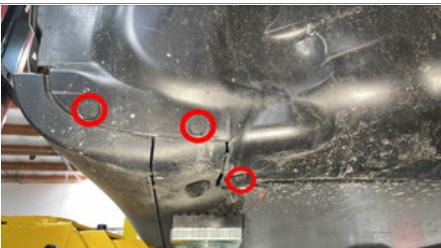
- Install clips securing RH wheel liner to rocker cover
NOTE:
3x clips, Re-position liner as needed
 Courtesy of TESLA, INC. Courtesy of TESLA, INC.
|
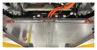
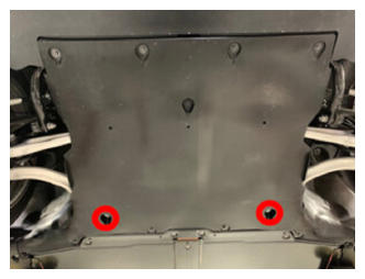
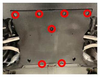
- Install front skid plate onto HV battery and secure bolts
NOTE:
4x bolts, EP10, 13 N.m, 2x bolts, 10mm, 5 N.m
 Courtesy of TESLA, INC. Courtesy of TESLA, INC.
|
 Courtesy of TESLA, INC. Courtesy of TESLA, INC.
|
- Lower vehicle partially and set onto locks
NOTE:
Raise lift off locks, then hold lock release lever to keep locks free while vehicle is lowered, Set vehicle to comfortable working height
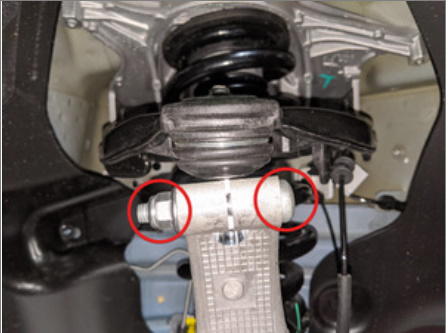
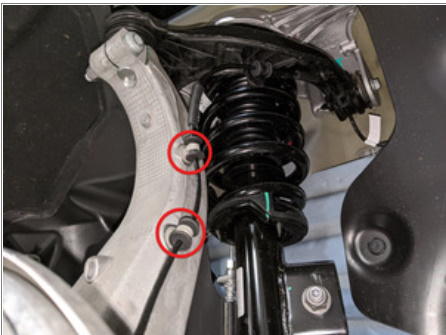
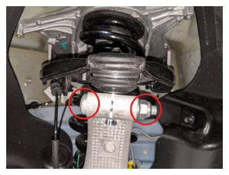
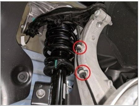
- Loosely install bolt and nut securing RH strut to RH front lower lateral link
NOTE:
1x bolt, 21mm, 1x nut, 21mm, 106 N.m, Torque at later step
 Courtesy of TESLA, INC. Courtesy of TESLA, INC.
|
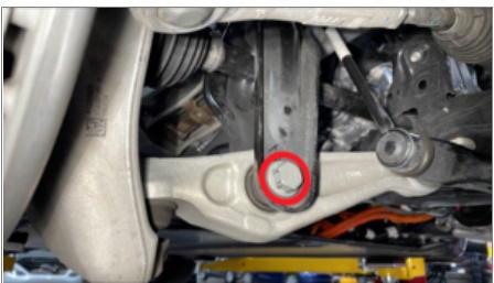
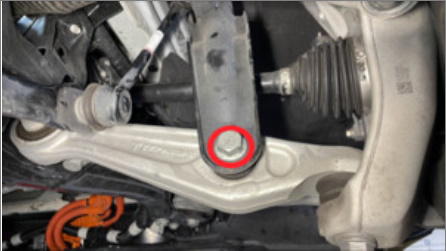
- Position the RH upper control arm to the knuckle and install nut and bolt
NOTE:
1x bolt, T50, 1x nyloc nut, 15mm, 56 N.m, Compress joint to install bolt, Install new nyloc nut
 Courtesy of TESLA, INC. Courtesy of TESLA, INC.
|
 Courtesy of TESLA, INC. Courtesy of TESLA, INC.
|
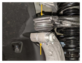
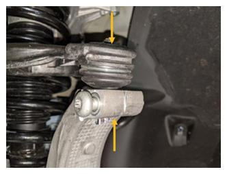
- Position front stabar end link onto RH front strut and secure nut
NOTE:
1x nyloc nut, 18mm, 98 N.m, Counter hold ball joint with T40, Install new fastener, Prybar can be used to relieve tension
 Courtesy of TESLA, INC. Courtesy of TESLA, INC.
|
 Courtesy of TESLA, INC. Courtesy of TESLA, INC.
|
 Courtesy of TESLA, INC. Courtesy of TESLA, INC.
|
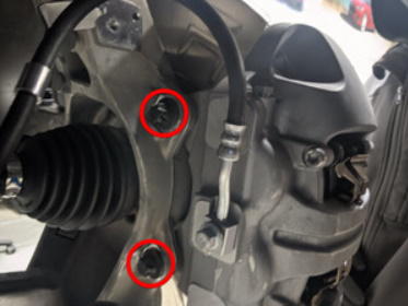
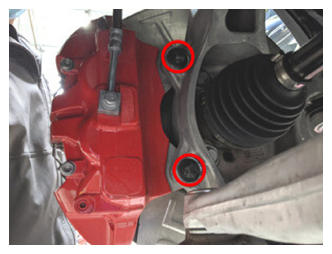
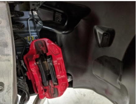
- Install RH front brake caliper to RH front knuckle
NOTE:
2x bolts, E18, 94 N.m, Install new bolts, Mark with paint pen, Remove S-hook from vehicle
 Courtesy of TESLA, INC. Courtesy of TESLA, INC.
|
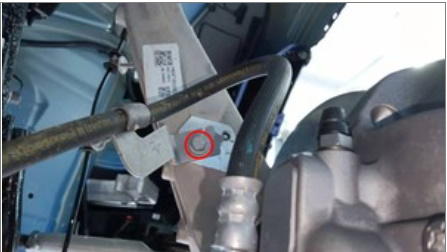
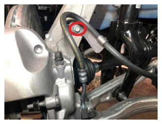
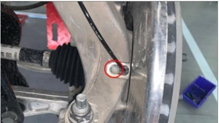
- Install bolt securing RH front brake caliper hose to RH front knuckle
NOTE:
1x bolt, 10mm, 5 N.m
 Courtesy of TESLA, INC. Courtesy of TESLA, INC.
|
- Install RH front wheel speed sensor harness to knuckle
NOTE:
2x harness clips
 Courtesy of TESLA, INC. Courtesy of TESLA, INC.
|
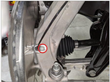
- Install bolt securing RH front wheel speed sensor to knuckle
NOTE:
1x bolt, 10mm, 5 N.m
 Courtesy of TESLA, INC. Courtesy of TESLA, INC.
|
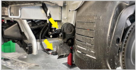
- Connect horn assembly connectors
NOTE:
2x connectors
 Courtesy of TESLA, INC. Courtesy of TESLA, INC.
|
- Loosely install bolt and nut securing LH strut to LH front lower lateral link
NOTE:
1x bolt, 21mm, 1x nut, 21mm, 106 N.m, Torque at later step
 Courtesy of TESLA, INC. Courtesy of TESLA, INC.
|
- Install bolt and nut securing LH front upper control arm to knuckle
NOTE:
1x bolt, T50, 1x nyloc nut, 15mm, 56 N.m, Compress joint to install bolt, Install new nyloc nut
 Courtesy of TESLA, INC. Courtesy of TESLA, INC.
|
 Courtesy of TESLA, INC. Courtesy of TESLA, INC.
|
- Position front stabar end link onto LH front strut and secure nut
NOTE:
1x nyloc nut, 18mm, 98 N.m, Counter hold ball joint with T40, Install new fastener, Prybar can be used to relieve tension
 Courtesy of TESLA, INC. Courtesy of TESLA, INC.
|
 Courtesy of TESLA, INC. Courtesy of TESLA, INC.
|
 Courtesy of TESLA, INC. Courtesy of TESLA, INC.
|
- Install bolt securing LH front brake caliper hose bracket to LH front knuckle
NOTE:
1x bolt, 10mm, 5 N.m
 Courtesy of TESLA, INC. Courtesy of TESLA, INC.
|
- Install LH front brake caliper to LH front knuckle
NOTE:
2x bolts, E18, 94 N.m, Install new bolts, Mark with paint pen, Remove S-hook from vehicle
 Courtesy of TESLA, INC. Courtesy of TESLA, INC.
|
 Courtesy of TESLA, INC. Courtesy of TESLA, INC.
|
- Install LH front wheel speed sensor harness to knuckle
NOTE:
2x harness clips
 Courtesy of TESLA, INC. Courtesy of TESLA, INC.
|
- Install bolt securing LH front wheel speed sensor to knuckle
NOTE:
1x bolt, 10mm, 5 N.m
 Courtesy of TESLA, INC. Courtesy of TESLA, INC.
|
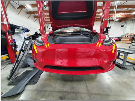
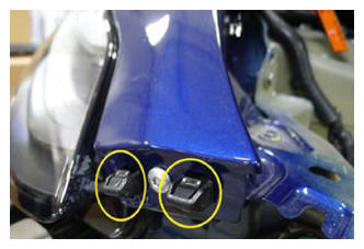
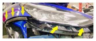
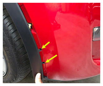
- Install front fascia onto vehicle and secure front clips and both front corners
NOTE:
8x clips, Recommend assistance, Use caution not to damage headlamp or fender during installation
 Courtesy of TESLA, INC. Courtesy of TESLA, INC.
|
 Courtesy of TESLA, INC. Courtesy of TESLA, INC.
|
 Courtesy of TESLA, INC. Courtesy of TESLA, INC.
|
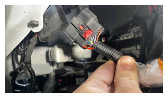
- Secure connection for the front fascia
NOTE:
1x locking connector, Secure connection and fully engage red locking tab
 Courtesy of TESLA, INC. Courtesy of TESLA, INC.
|
 Courtesy of TESLA, INC. Courtesy of TESLA, INC.
|
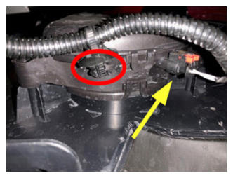
- Secure connection and clip for pedestrian warning speaker
NOTE:
1x connector, 1x clip, Engage locking tab
 Courtesy of TESLA, INC. Courtesy of TESLA, INC.
|
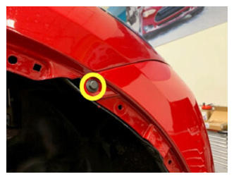
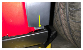
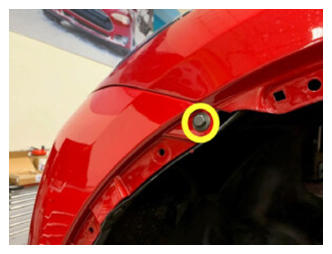
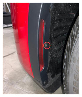
- Install bolt securing RH side of fascia to fender
NOTE:
1x bolt, 10mm, 4 N.m
 Courtesy of TESLA, INC. Courtesy of TESLA, INC.
|
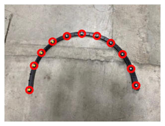
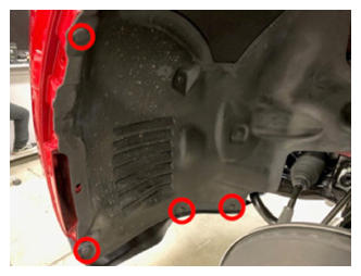
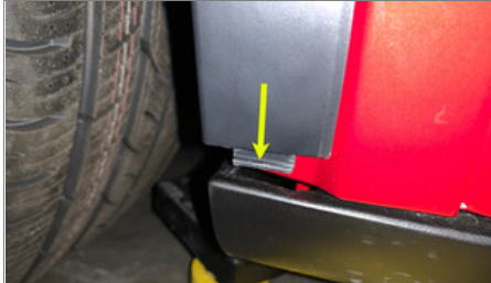
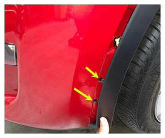
- Install RH front fender garnish
NOTE:
11x clips, 1x push clip, 3x tabs, Start at rear and maneuver into rocker panel
 Courtesy of TESLA, INC. Courtesy of TESLA, INC.
|
 Courtesy of TESLA, INC. Courtesy of TESLA, INC.
|
 Courtesy of TESLA, INC. Courtesy of TESLA, INC.
|
 Courtesy of TESLA, INC. Courtesy of TESLA, INC.
|
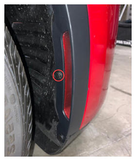
- Install bolt securing LH side of fascia to fender
NOTE:
1x bolt, 10mm, 4 N.m
 Courtesy of TESLA, INC. Courtesy of TESLA, INC.
|
- Install clips securing LH wheel liner to fascia
NOTE:
4x push clips
 Courtesy of TESLA, INC. Courtesy of TESLA, INC.
|
- Install LH front fender garnish
NOTE:
12x clips, 3x tabs, Start at rear and maneuver into rocker panel, Be cautious not to bend front tabs going into front fascia
Courtesy of TESLA, INC.
|
 Courtesy of TESLA, INC. Courtesy of TESLA, INC.
|
 Courtesy of TESLA, INC. Courtesy of TESLA, INC.
|
 Courtesy of TESLA, INC. Courtesy of TESLA, INC.
|
- Raise vehicle fully and lower lift onto locks
NOTE:
Set vehicle to comfortable working height, Make sure there's an audible click of the locks on both sides before lowering, otherwise vehicle may tilt to the side
- Position the front aero shield to vehicle and install nuts
NOTE:
2x nuts, 15mm, 5 N.m
 Courtesy of TESLA, INC. Courtesy of TESLA, INC.
|
- Apply Loctite 222 onto front aero shield bolts and install outer fasteners to front aero shield
NOTE:
7x bolts, 10mm, 5 N.m
 Courtesy of TESLA, INC. Courtesy of TESLA, INC.
|
- Lower vehicle partially and set lift onto locks
NOTE:
Note Raise lift off locks, then hold lock release lever to keep locks free while vehicle is lowered, Set vehicle to comfortable working height
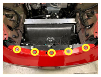
- Install fasteners holding upper portion of front fascia to vehicle
NOTE:
5x bolts, 10mm, 4 N.m
 Courtesy of TESLA, INC. Courtesy of TESLA, INC.
|
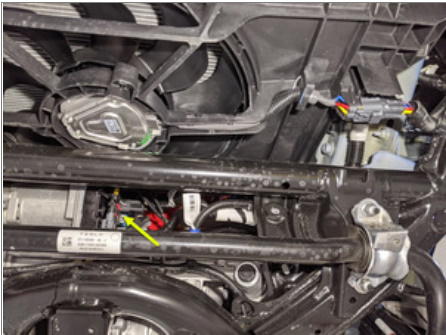
- Connect the logic connectors below steering gear
NOTE:
2x connectors, Engage locking tabs
 Courtesy of TESLA, INC. Courtesy of TESLA, INC.
|
 Courtesy of TESLA, INC. Courtesy of TESLA, INC.
|
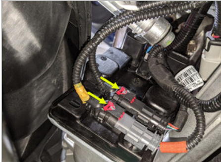
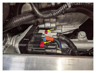
- Connect the steering gear assembly connectors
NOTE:
2x locking connectors, Engage locking tab
 Courtesy of TESLA, INC. Courtesy of TESLA, INC.
|
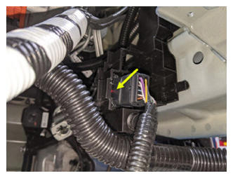
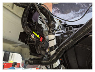
- Secure connection for the front subframe harness
NOTE:
1x locking connector, Red locking tab, Connect from front of bracket and lock from opposite side of bracket
 Courtesy of TESLA, INC. Courtesy of TESLA, INC.
|
 Courtesy of TESLA, INC. Courtesy of TESLA, INC.
|
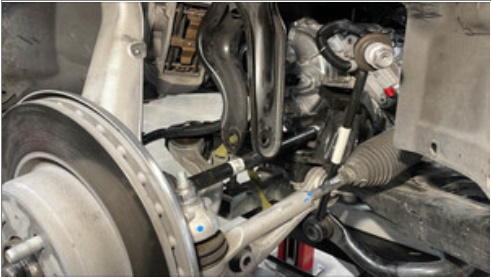
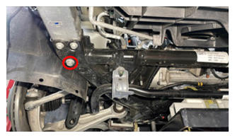
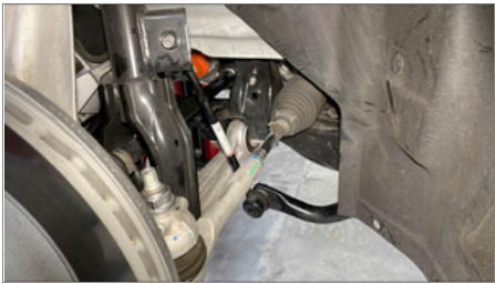
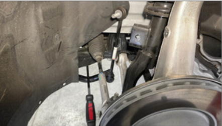
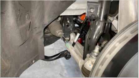
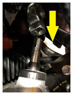
- Slide the intermediate shaft assembly downward to install it to the steering gear assembly
NOTE:
Ensure the intermediate shaft is aligned and fully seated, if necessary to align the shaft to steering gear
 Courtesy of TESLA, INC. Courtesy of TESLA, INC.
|
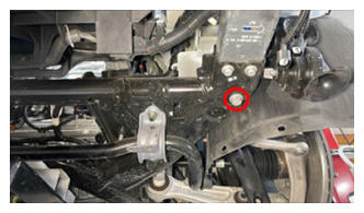
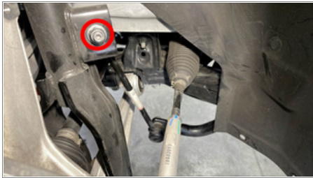
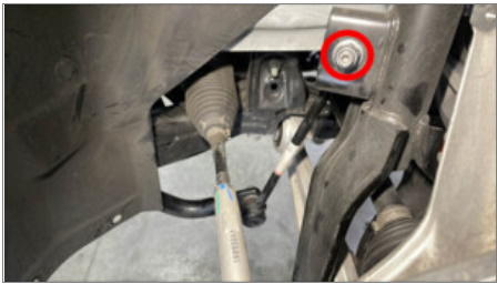
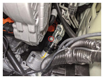
- Install bolt securing the intermediate shaft assembly to the steering gear assembly
NOTE:
1x bolt, 13mm, 18 N.m
 Courtesy of TESLA, INC. Courtesy of TESLA, INC.
|
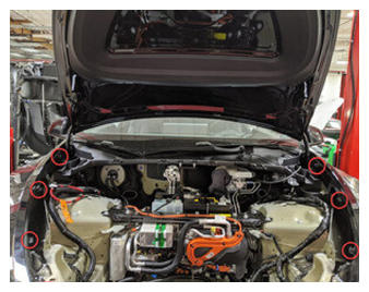
- Install frunk assembly into vehicle
NOTE:
6x clips, Replace any clips if broken or missing
 Courtesy of TESLA, INC. Courtesy of TESLA, INC.
|
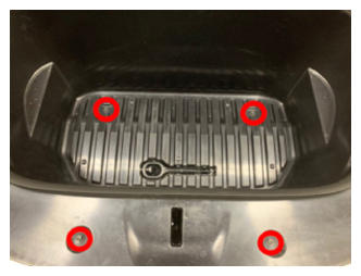
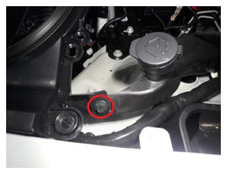
- Install fasteners securing the frunk assembly
NOTE:
5x bolts, 10mm, 5 N.m, Newer vehicles may be equipped with 1x push clip securing frunk to washer bottle neck
 Courtesy of TESLA, INC. Courtesy of TESLA, INC.
|
 Courtesy of TESLA, INC. Courtesy of TESLA, INC.
|
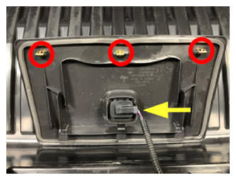
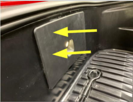
- Install access panel
NOTE:
3x clips, 1x connector
 Courtesy of TESLA, INC. Courtesy of TESLA, INC.
|
 Courtesy of TESLA, INC. Courtesy of TESLA, INC.
|
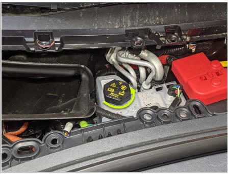
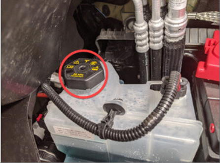
- Remove coolant bottle cap
 Courtesy of TESLA, INC. Courtesy of TESLA, INC.
|
- Place empty coolant container into front storage area
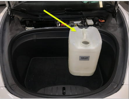 Courtesy of TESLA, INC. Courtesy of TESLA, INC.
|
- Fill container with at least 15L of coolant
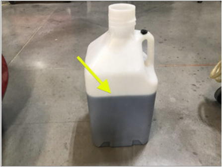 Courtesy of TESLA, INC. Courtesy of TESLA, INC.
|
- Place filled coolant container into front storage area
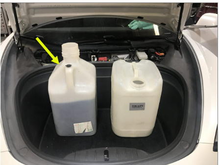 Courtesy of TESLA, INC. Courtesy of TESLA, INC.
|
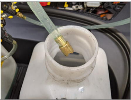
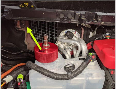
- Install refill tool cap onto coolant bottle assembly
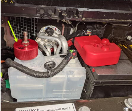 Courtesy of TESLA, INC. Courtesy of TESLA, INC.
|
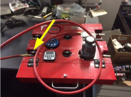
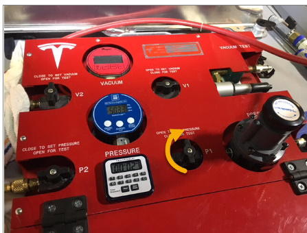
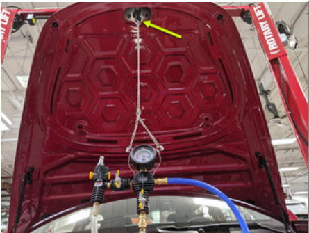
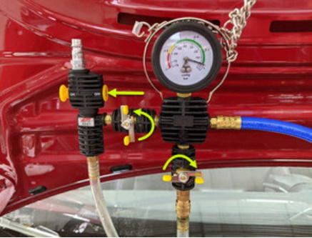
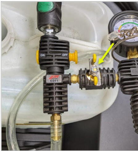
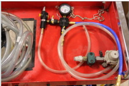
- Setup vacuum refill tool
NOTE:
Verify all valves on refill tool are in the closed position, See image for clarity
 Courtesy of TESLA, INC. Courtesy of TESLA, INC.
|
 Courtesy of TESLA, INC. Courtesy of TESLA, INC.
|
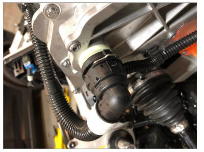
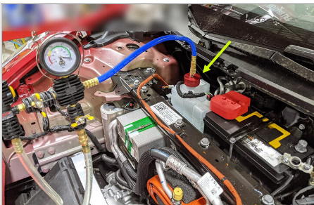
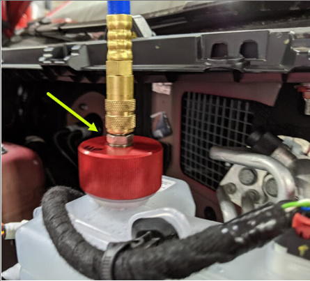
- Install vacuum refill hose into refill cap on coolant bottle
NOTE:
Perform push-pull-push test to verify hose is fully engaged
 Courtesy of TESLA, INC. Courtesy of TESLA, INC.
|
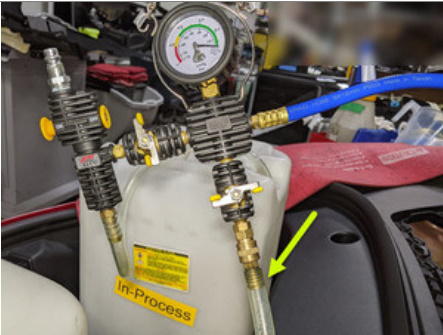
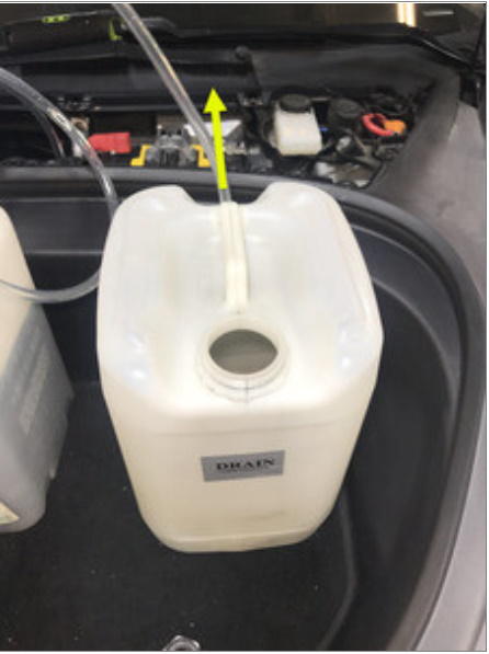
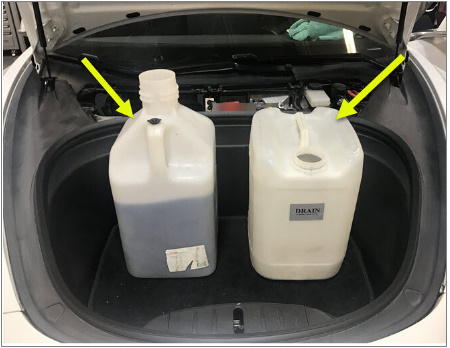
- Place refill hose inside filled coolant container
NOTE:
Make sure hose end is fully submerged into coolant
 Courtesy of TESLA, INC. Courtesy of TESLA, INC.
|
 Courtesy of TESLA, INC. Courtesy of TESLA, INC.
|
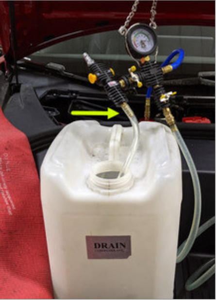
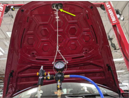
- Position overflow hose into empty container
 Courtesy of TESLA, INC. Courtesy of TESLA, INC.
|
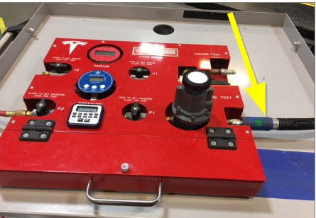
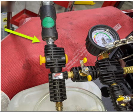
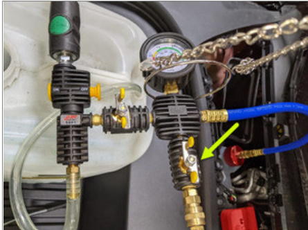
- Connect shop air supply to coolant refill tool
NOTE:
If not already done, Verify refill valve is set to off
 Courtesy of TESLA, INC. Courtesy of TESLA, INC.
|
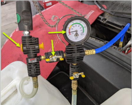
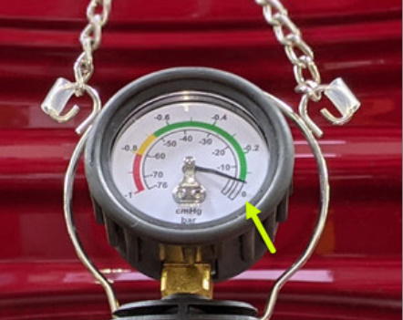
- Open air inlet valve to draw a vacuum, Once gauge stabilizes, Fully close valve
NOTE:
Gauge stabilizes roughly (60-70 cmHg), Vacuum should not drop after the valves are closed
 Courtesy of TESLA, INC. Courtesy of TESLA, INC.
|
 Courtesy of TESLA, INC. Courtesy of TESLA, INC.
|
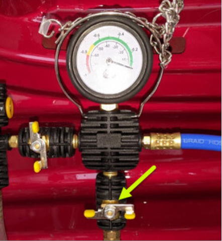
- Slowly open the refill valve to allow coolant to be drawn into the system
NOTE:
Make sure hose end of refill hose is fully submerged during entire process
 Courtesy of TESLA, INC. Courtesy of TESLA, INC.
|
- Once the gauge reads zero, close the refill valve
 Courtesy of TESLA, INC. Courtesy of TESLA, INC.
|
 Courtesy of TESLA, INC. Courtesy of TESLA, INC.
|
- Disconnect shop air supply from coolant refill tool
Courtesy of TESLA, INC.
|
- Remove coolant refill hose from coolant container
Courtesy of TESLA, INC.
|
- Remove coolant overflow hose from coolant container
 Courtesy of TESLA, INC. Courtesy of TESLA, INC.
|
- Remove vacuum refill hose from refill cap on coolant bottle
 Courtesy of TESLA, INC. Courtesy of TESLA, INC.
|
- Remove refill tool cap from coolant bottle assembly
 Courtesy of TESLA, INC. Courtesy of TESLA, INC.
|
- Remove coolant refill tool from vehicle
 Courtesy of TESLA, INC. Courtesy of TESLA, INC.
|
 Courtesy of TESLA, INC. Courtesy of TESLA, INC.
|
- Remove both coolant containers from inside underhood area
 Courtesy of TESLA, INC. Courtesy of TESLA, INC.
|
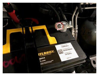
- Connect first responder loop and 12V negative terminal
NOTE:
1x nut, 10mm, 6 N.m, 1x connector, Engage locking tab, Connect FRL first before connecting 12V to avoid damage to car computer
 Courtesy of TESLA, INC. Courtesy of TESLA, INC.
|
 Courtesy of TESLA, INC. Courtesy of TESLA, INC.
|
- Move RH front seat to original position
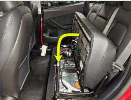
- Reposition 2nd row seat cushion
NOTE:
Slide cushion rearward then align with buckles and foam with seat rail, Make sure cushion is fully seated with push & pull test
 Courtesy of TESLA, INC. Courtesy of TESLA, INC.
|
- Move LH front seat to original position
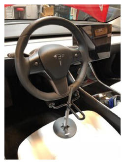
- Remove the steering wheel holder
 Courtesy of TESLA, INC. Courtesy of TESLA, INC.
|
- Re-establish vehicle connection to Toolbox 3.0
- Select 'Actions/Autodiag' and search for 'Thermal'
- Select 'Stop Thermal Fluid Fill/Drain', click 'Run', and allow routine to complete
- Select 'Actions/Autodiag' tab and search for 'Purge'
- Select 'TEST_VCFRONT_X_THERMAL-COOLANT-AIR-PURGE ', click 'Run', and allow routine to complete
NOTE:
Make sure vehicle is not in drive state, Plan is still running despite the stop message, Coolant pumps will be audible, Test lasts approximately 10 mins, Speeds can be monitored in garage under PT Thermal tab, Idle speed = ~1500 RPM, Test will vary speeds from 3500-6500 RPM and actuate valve between SERIES and PARALLEL, Putting vehicle into drive state will stop this routine, If speeds hover at 7000 RPM, that means the pumps are air locked, perform vacuum fill again, Continue to add coolant and purge until the coolant level reaches between the NOM and MAX Lines on the bottle, Select 'X' at top right of window to close once complete
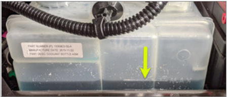
- Inspect coolant level and top off as necessary
NOTE:
Ensure coolant is filled using G-48 coolant
 Courtesy of TESLA, INC. Courtesy of TESLA, INC.
|
- Install coolant bottle cap
 Courtesy of TESLA, INC. Courtesy of TESLA, INC.
|
- Remove HSD or RJ45 cable from Ethernet port to disconnect Toolbox 3.0 from vehicle
- Raise vehicle partially and lower lift onto locks
NOTE:
Set vehicle to a comfortable working height, Make sure there's an audible click of the locks on both sides before lowering, otherwise vehicle may tilt to the side
- Install RH front wheel
NOTE:
5x nuts, 21mm, 175 N.m, Start lug nuts by hand before using power tool
- Install LH front wheel
NOTE:
5x nuts, 21mm, 175 N.m, Start lug nuts by hand before using power tool
- Lower vehicle until tires are touching the ground
NOTE:
Raise lift off locks, then hold lock release lever to keep locks free while vehicle is lowered
- Torque LH front wheel
NOTE:
5x nuts, 21mm, 175 N.m
- Install LH front wheel cap
NOTE:
1x cap, Align valve stem with wheel cap cavity
- Torque RH front wheel
NOTE:
5x nuts, 21mm, 175 N.m
- Install RH front wheel cap
NOTE:
1x cap, Align valve stem with wheel cap cavity
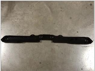
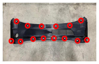
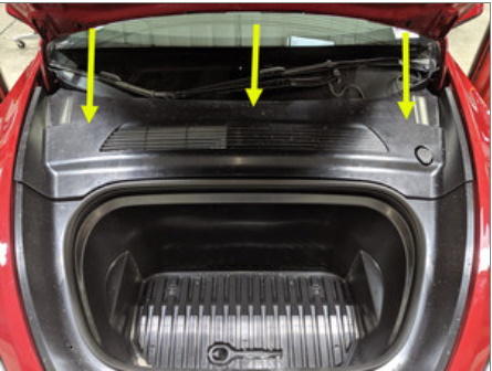
- Install rear apron
NOTE:
14x clips, Hold rear wall of frunk to keep from flexing while engaging front clips
 Courtesy of TESLA, INC. Courtesy of TESLA, INC.
|
 Courtesy of TESLA, INC. Courtesy of TESLA, INC.
|
- Close hood
- Remove vehicle from lift
NOTE:
Lower rack arms fully and remove from under vehicle
- Raise all four windows
- Close all four doors
NOTE:
If 12V is powered up, Unlatch rear doors before closing
- Review wheel alignment requirements and add correction code as needed
NOTE:
Note https://service.tesla.com/docs/ModelY/ServiceManual/en-us/GUID-FBF882A5-F87B-48A7-AC03-3AF71C2B11E5.html