September 30: LEMON manuals is back up on a temporary server! Slowness is possible
Diagnosis & Repair
- If Toyota hand-held tester is available, go to next step. If Toyota hand-held tester is not available, go to step 6.
- Connect hand-held tester to Data Link Connector (DLC) No. 3 at driver's side of instrument panel. See Figure. Turn ignition on and then turn hand-held tester on. Using hand-held tester, monitor NSW, REVERSE, 2ND and LOW signals while moving shift lever into Park, Reverse, Neutral, "2" and Low. Ensure signals are properly displayed in relation to shift lever position. See INPUT SIGNAL DISPLAYS table. If signals are not properly displayed, go to next step. If signals are properly displayed, replace ECM. ECM is located behind glove box, near passenger's side kick panel. See Figure.
INPUT SIGNAL DISPLAYS
| Shift Lever Position |
Signal Display |
| Park & Neutral |
NSW OFF-ON |
| Reverse |
REVERSE OFF-ON |
| Low |
LOW OFF-ON |
| 2 |
2ND OFF-ON |
- Disconnect electrical connector from PNP switch. PNP switch is located on side of transaxle. Note PNP switch terminal identification. See Fig 1. Using ohmmeter, check for continuity between specified terminals with shift lever in proper positions. See PARK/NEUTRAL POSITION SWITCH SPECIFICATIONS table.
- If proper continuity exists, go to next step. If proper continuity does not exist, adjust or replace switch as necessary. For adjustment or replacement procedures for PNP switch, adjustment of PNP switch, see PARK/NEUTRAL POSITION SWITCH
under ENGINE SENSORS & SWITCHES in REMOVAL, OVERHAUL & INSTALLATION - V6 & V8 article.
PARK/NEUTRAL POSITION SWITCH SPECIFICATIONS
| Shift Lever Position |
Continuity Between Terminals No. |
| Park |
2 & 7; 5 & 6 |
| Reverse |
2 & 8 |
| Neutral |
2 & 9; 5 & 6 |
| Drive |
2 & 10 |
| 2 |
2 & 3 |
| Low |
2 & 4 |
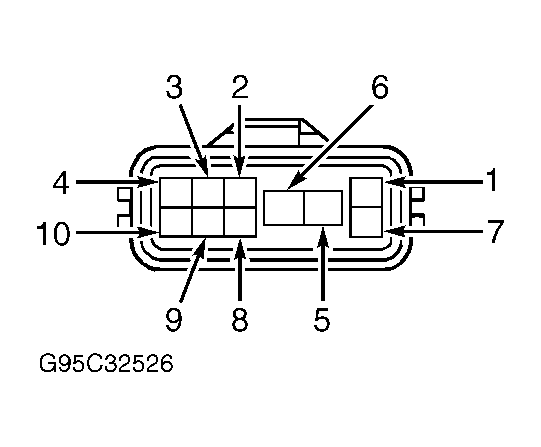 Courtesy of © TOYOTA, LICENSE AGREEMENT TMS1002
- Check for defective wiring harness and electrical connectors between PNP switch and ECM, and between battery and PNP switch. See WIRING DIAGRAMS
article. It may be necessary to consult wiring diagram in appropriate STARTERS article in STARTING & CHARGING SYSTEMS for additional PNP switch wiring. ECM is located behind glove box, near passenger's side kick panel. See Figure. Repair wiring harness or electrical connectors as necessary.
- Remove glove box for access to ECM with electrical connectors still installed on ECM. See Figure. Turn ignition on. Using voltmeter, check voltage between body ground and specified terminal at ECM electrical connectors E6 and E7 in relation to shift lever position. See PARK/NEUTRAL POSITION SWITCH VOLTAGE table. See Figure. If voltage is not within specification, go to next step. If voltage is within specification, replace ECM.
PARK/NEUTRAL POSITION SWITCH VOLTAGE
| Shift Lever Position |
ECM Electrical Connector & Terminal No. |
Volts |
| Park & Neutral |
E6 Terminal No. 8 |
0 |
| E6 Terminal No. 13 |
0 |
| E6 Terminal No. 14 |
0 |
| E7 Terminal No. 20 |
0 |
| Reverse |
E6 Terminal No. 8 |
9-14 |
| E6 Terminal No. 13 |
0 |
| E6 Terminal No. 14 |
0 |
| E7 Terminal No. 20 |
9-14 |
| Drive |
E6 Terminal No. 8 |
0 |
| E6 Terminal No. 13 |
0 |
| E6 Terminal No. 14 |
0 |
| E7 Terminal No. 20 |
9-14 |
| 2 |
E6 Terminal No. 8 |
0 |
| E6 Terminal No. 13 |
0 |
| E6 Terminal No. 14 |
9-14 |
| E7 Terminal No. 20 |
9-14 |
| Low |
E6 Terminal No. 8 |
0 |
| E6 Terminal No. 13 |
9-14 |
| E6 Terminal No. 14 |
0 |
| E7 Terminal No. 20 |
9-14 |
- Disconnect electrical connector from PNP switch. PNP switch is located on side of transaxle. Note PNP switch terminal identification. See Fig 1. Using ohmmeter, check for continuity between specified terminals with shift lever in proper positions. See PARK/NEUTRAL POSITION SWITCH SPECIFICATIONS table.
- If proper continuity exists, go to next step. If proper continuity does not exist, adjust or replace PNP switch as necessary. For adjustment or replacement procedures for PNP switch, see PARK/NEUTRAL POSITION SWITCH
under ENGINE SENSORS & SWITCHES in REMOVAL, OVERHAUL & INSTALLATION - V6 & V8 article.
- Check for defective wiring harness and electrical connectors between PNP switch and ECM, and between battery and PNP switch. See WIRING DIAGRAMS
article. It may be necessary to consult wiring diagram in appropriate STARTERS article in STARTING & CHARGING SYSTEMS for additional PNP switch wiring. Repair wiring harness or electrical connectors as necessary.