System Diagnosis
On California models equipped with Digifant II system, an "On-Board Diagnostic System" is used. Trouble codes/fault memory can be read through the "Check" indicator switch which illuminates when a fault is detected and stored in memory or by activating fault memory. To activate fault memory/code(s), turn ignition switch to "ON" position, engine off. Depress "Check" indicator switch for at least 4 seconds. Indicator light on switch will start flashing codes. A flash code consists of 4 flash impulse groups, with a maximum of 4 flash impulse per group. Between each impulse group there is a 2.5 second pause between codes.
To erase fault codes from memory, turn ignition switch to "OFF" position, press and hold down indicator switch and turn ignition switch to "ON" position. Continue depressing switch for about 5 seconds and turn ignition switch off. Test drive vehicle for a minimum of 10 minutes. Recheck codes and correct if necessary. Repeat fault erasing procedure until memory is cleared.
FAULT/TROUBLE CODES - DIGIFANT II
| Flash Code |
Circuit Affected |
| 2312 |
Coolant Temperature Sensor |
| 2322 |
Intake Air Temperature Sensor |
| 2232 |
Airflow Sensor Potentiometer |
| 2142 |
Knock Sensor |
| 2342 |
Oxygen Sensor |
| 4444 |
No Fault(s) in Memory |
| 0000 |
End of Test Sequence |
 Courtesy of VOLKSWAGEN UNITED STATES, INC.
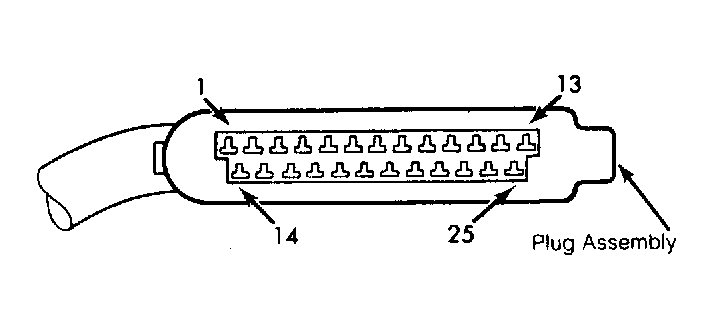
 GOLF, GOLF GT & JETTA AFC DIGIFANT SYSTEM RESISTANCE CHECKS
| Terminals |
Components Checked |
Specifications |
| No. 12 & No. 14 |
Injectors |
15-20 ohms with only 1 injector connected |
| No. 6
& No. 11 |
Throttle Valve Switch (Idle & Full) |
0 ohms at idle & full throttle |
| No. 2 & No. 13 |
Oxygen Sensor |
0 ohms with O2 sensor disconnected & grounded/infinity with sensor connected |
| No. 6
& No. 17 |
Airflow Meter |
Approximately 500-1000 ohms |
| No. 21 & No. 17 |
Airflow Meter |
Ohms varies when moving air sensor |
| No. 6
& No. 8/No. 6
& No. 18 |
Hall Sender Wiring |
Continuity should exist w/sensor removed & all 3 connectors jumped together |
| No. 4 & No. 5/No. 4 & No. 7 |
Knock Sensor |
Continuity should exist w/sensor removed & all 3 connectors jumped together |
| No. 22 & No. 23 |
Idle Stabilizer |
Continuity |
| No. 16 & No. 13 |
A/C Compressor |
Continuity should exist w/Green wire on brake booster grounded |
GOLF, GOLF GT & JETTA AFC DIGIFANT SYSTEM VOLTAGE CHECKS
| Terminals |
Components Checked |
Specifications |
| No. 13 & No. 14/No. 14 & No. 19 |
ECU Voltage Supply |
About battery voltage |
| No. 13 & No. 25 |
To Ignition Coil Term. 1 |
About battery voltage |
| No. 1 & No. 13 |
Voltage to Idle Stabilizer |
Pull injector plugs off. Cranking voltage should be present when cranking engine |
| No. 3 & No. 13 |
Fuel Pump Relay |
Place jumper wire across terminals. Turn ignition on and fuel pump must run |
VANAGON AFC DIGIFANT SYSTEM RESISTANCE CHECKS
| Terminals |
Components Checked |
Specifications |
| No. 12 & No. 14 |
Injectors |
Connect only one injector at a time. 15-20 ohms |
| No. 6
& No. 11 |
Throttle Valve Switch |
Continuity when closed or fully open |
| No. 6
& No. 17 |
Intake Air Sensor |
500-1000 ohms |
| No. 17 & No. 21 |
Intake Air Sensor |
Resistance changes when moving air sensor plate |
| No. 6
& No. 8/No. 6
& No. 18 |
Hall Sender Wiring |
Continuity should exist with Hall sender removed and all 3 connectors jumped together |
| No. 2 & No. 13 |
Oxygen Sensor Wiring |
Continuity should exist with connector removed from oxygen sensor and Green wire grounded. No continuity with connector installed |
VANAGON AFC DIGIFANT SYSTEM VOLTAGE CHECKS
| Terminals |
Components Checked |
Specifications |
| No. 13 & No. 14/No. 14 & No. 19 |
Control Unit Voltage Supply |
Approximate battery voltage |
| No. 13 & No. 25 |
Voltage To Ignition Coil Terminal No. 1 |
Approximate battery voltage |
| No. 1 & No. 13 |
Voltage To Idle Stabilizer |
Unplug all 4 injectors. Voltage at starter terminal No. 50 when cranking should be minimum 8 volts |
| No. 3 & No. 13 |
Voltage To Fuel Pump Relay |
Connect jumper wire between terminals. Fuel pump should operate |