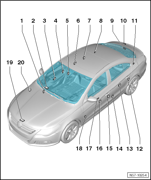
Central Locking Component Location Overview
 Courtesy of VOLKSWAGEN GROUP OF AMERICA, INC.
- Connector station
- Installed location: right A-pillar
- To disconnect harness connector, release bellows at pillar. Refer to DOOR
- Comfort system central control module -J393-
- Front passenger door control module -J387-
- Front passenger central locking lock unit -F221-
- Door lock is secured to subframe.
- Electrical central locking system is integrated in door lock.
- Removing, refer to DOOR LOCK
- Connector station
- Installed location: right B-pillar
- To disconnect harness connector, release bellows at pillar
- Right rear door control module -J389-
- Right rear central locking lock unit -F223-
- Door lock is secured to subframe.
- Electrical central locking system is integrated in door lock.
- Removing, refer to DOOR LOCK
- Fuel tank lid unlock motor -V155-
- Installed location: behind the luggage compartment trim panel on the right side
- Removing, refer to ACTUATOR
- Release button in rear lid handle -E234-
- Installed location: inside the emblem
- Removing, refer to ACTUATOR
- Rear lid lock unit -F256-
- Installed location: attached to the rear lid
- Removing and Installing, refer to REAR LID LATCH
- Rear lid connector station
- Installed location: behind the luggage compartment trim panel on the left side
- Removing and installing. Refer to Removal and Installation
- Left rear central locking lock unit -F222-
- Door lock is secured to subframe.
- Electrical central locking system is integrated in door lock.
- Removing, refer to DOOR LOCK
- Left rear door control module -J388-
- Connector station
- Installed location: left B-pillar
- To disconnect harness connector, release bellows at pillar
- Driver central locking lock unit -F220-
- Door lock is secured to subframe.
- Electrical central locking system is integrated in door lock.
- Removing, refer to DOOR LOCK
- Driver door control module -J386-
- Central window regulator switch in driver door -E189-
- Connector station
- Installed location: left A-pillar
- To disconnect harness connector, release bellows at pillar DOOR
- Engine hood contact switch -F266-
- Alarm horn -H12-
- Installed location: under the right fender
- Removing. Refer to ALARM HORN H12