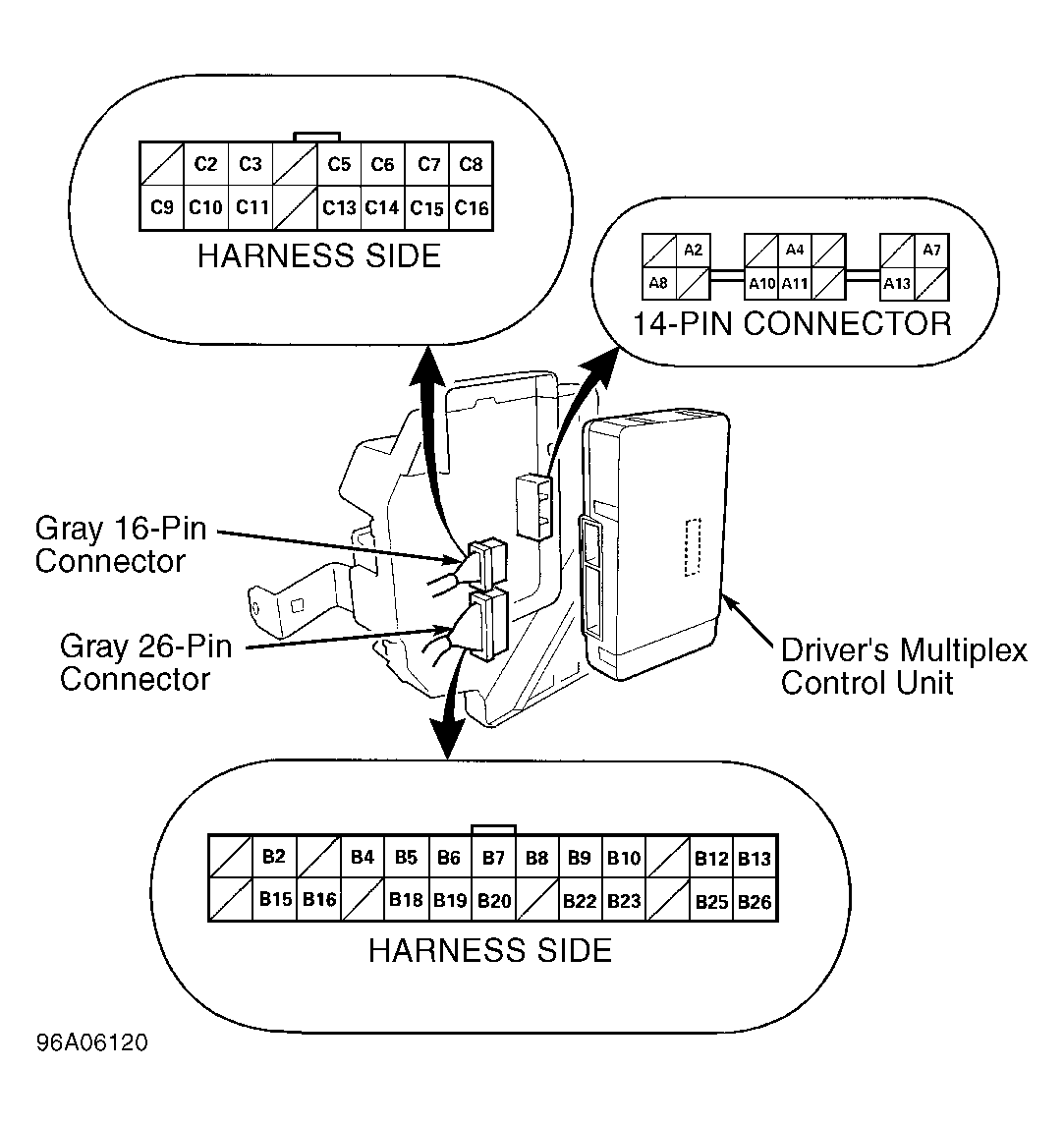
Driver's Multiplex Control Unit
- Remove fuse/relay box located under instrument panel. Turn ignition switch to OFF position. Disconnect driver's multiplex control unit from instrument panel fuse/relay box. See Fig 1
. Disconnect multiplex control unit Gray 16-pin and Gray 26-pin connectors. Ensure terminals of connectors are okay and making proper contact. Repair connector terminals as necessary and retest system. If connector terminals are okay without reconnecting control unit connectors, go to next step.
- Using a voltmeter, probe between fuse/relay box 14-pin connector terminal A8 and ground. See Fig 1
. See procedures under DRIVER'S MULTIPLEX CONTROL UNIT CONNECTOR TERMINAL IDENTIFICATION table. If voltage is less than one volt, go to next step. If voltage is one volt or more, check for an open in Black wire or a poor ground. See WIRING DIAGRAMS
. Repair as necessary and retest system.
- Using a voltmeter, probe between fuse/relay box 14-pin connector terminal A13 and ground. Turn ignition switch to ON position and measure voltage. If battery voltage exists, go to next step. If battery voltage does not exist, check fuse No. 13 (7.5-amp), located in fuse/relay box under instrument panel. See Figure
. If fuse is okay, check for an open in fuse/relay box circuit between fuse No. 13 and terminal A13. See WIRING DIAGRAMS
. Repair as necessary and retest system.
- Turn ignition switch to OFF position. Using a fused jumper wire, ground multiplex control unit Gray 26-pin connector terminal B4 (Red/Green wire). If taillights illuminate, go to next step. If taillights do not illuminate, check taillight relay and/or for a faulty circuit in taillight system. See WIRING DIAGRAMS
. Repair as necessary and retest system.
- Turn ignition switch to ON position. Using a fused jumper wire, ground multiplex control unit Gray 26-pin connector terminal B7 (White wire). If security indicator light illuminates, go to next step. If security indicator light does not illuminate, check fuse No. 56 (7.5-amp), located in fuse/relay box under instrument panel. If fuse is okay, check indicator light bulb and/or for an open in circuit. See WIRING DIAGRAMS
. Repair as necessary and retest system.
- Turn ignition switch to OFF position. Using a fused jumper wire, ground multiplex control unit Gray 26-pin connector terminal B8 (Orange wire). If horns sound, go to next step. If horns do not sound, check fuse No. 56 (7.5-amp), located in fuse/relay box under instrument panel. If fuse is okay, check horn relay, horns, ground connection or for an open circuit. See WIRING DIAGRAMS
. Repair as necessary and retest system.
- Ensure ignition switch is in OFF position. Using a fused jumper wire, ground multiplex control unit Gray 26-pin connector terminal B16 (Blue/Red wire). If headlights illuminate, go to next step. If headlights do not illuminate, check headlight relay and/or for a faulty circuit in headlight system. See WIRING DIAGRAMS
. Repair as necessary and retest system.
- Reconnect driver's multiplex control unit Gray 16-pin and Gray 26-pin connectors. Using a voltmeter, backprobe between 16-pin connector terminal C7 (Gray wire) and ground. Lock and unlock left rear door lock knob and measure voltage. In UNLOCK position, voltage should be 5 volts or more. In LOCK position, voltage should be less than one volt. If voltage is as specified, go to next step. If voltage is not as specified, check left rear door lock actuator. See DOOR LOCKS - POWER & TRUNK RELEASE article in the ACCESSORIES/SAFETY EQUIPMENT section. If actuator is okay, check ground connections or for an open circuit. See WIRING DIAGRAMS
. Repair as necessary and retest system.
- Using a voltmeter, backprobe between 16-pin connector terminal C8 (Green/Orange wire) and ground. Lock and unlock trunk key cylinder switch and measure voltage. In LOCK position, voltage should be 5 volts or more. In UNLOCK position, voltage should be less than one volt. If voltage is as specified, go to next step. If voltage is not as specified, check trunk key cylinder switch. See TRUNK KEY CYLINDER SWITCH TEST under COMPONENT TESTS
. If trunk key cylinder switch is okay, check ground connections or for an open circuit. See WIRING DIAGRAMS
. Repair as necessary and retest system.
- Using a voltmeter, backprobe between 16-pin connector terminal C9 (Blue/White wire) and ground. Insert and remove ignition key into and out of ignition switch and measure voltage. With key inserted into ignition switch, voltage should be 5 volts or more. With key removed from ignition switch, voltage should be less than one volt. If voltage is as specified, go to next step. If voltage is not as specified, check ignition key switch. See IGNITION KEY SWITCH TEST under COMPONENT TESTS
. If ignition key switch is okay, check ground connections or for an open circuit. See WIRING DIAGRAMS
. Repair as necessary and retest system.
- Using a voltmeter, backprobe between 16-pin connector terminal C15 (Green/Yellow wire) and ground. Open and close left rear door and measure voltage. With door closed, voltage should be 5 volts or more. With door open, voltage should be less than one volt. If voltage is as specified, replace driver's multiplex control unit. If voltage is not as specified, check left rear door switch. See DOOR LOCKS - POWER & TRUNK RELEASE article in the ACCESSORIES/SAFETY EQUIPMENT section. If door switch is okay, check ground connections or for an open in Green/Yellow wire. See WIRING DIAGRAMS
. Repair as necessary and retest system.
 Courtesy of AMERICA HONDA MOTOR CO., INC.
 DRIVER'S MULTIPLEX CONTROL UNIT CONNECTOR TERMINAL IDENTIFICATION
| Terminal (Wire Color) |
Circuit |
| 14-Pin Connector |
| A2 |
Wiper Park Position Input |
| A4 |
Vehicle Speed Sensor (VSS) Input |
| A7 |
Battery Input |
| A8 |
Ground |
| A10 |
Multiplex Control Inspection Connector Input |
| A11 |
Power Window Relay Control |
| A13 |
Ignition Input |
| Gray 26-Pin Connector |
| B2 (BLK/RED) |
Key Interlock Switch Input |
| B4 (RED/GRN) |
Lights-On Input/Taillight Relay Control |
| B5 (GRN) |
Intermittent ON Input |
| B6 (GRN/YEL) |
Intermittent Dwell Timer Input |
| B7 (WHT) |
Security Indicator Light Control |
| B8 (ORG) |
Horn Control |
| B9 (BRN/WHT) |
D-A Line |
| B10 (PNK/BLU) |
Wake-Up |
| B12 (GRN/WHT) |
Brake Switch Input |
| B13 (WHT/RED) |
Key Interlock Solenoid Control |
| B15 (PNK) |
Keyless Buzzer Control |
| B16 (BLU/RED) |
Headlight Relay Control |
| B18 (GRN/RED) |
Intermittent Wiper Control |
| B19 (GRN/WHT) |
Intermittent Dwell Timer Input |
| B20 (BLK/WHT) |
Wiper ON Input |
| B22 (RED/YEL) |
A-D Line |
| B23 (BRN/YEL) |
Door D-Line |
| B25 (WHT/BLK) |
Ignition Key Light Control |
| B26 (WHT/GRN) |
Shift Lock Circuit Input |
| Gray 16-Pin Connector |
| C2 (BLK/BLU) |
Park Position Switch |
| C3 (LT GRN) |
Instrument Cluster Illumination Brightness Control |
| C5 (WHT/BLK) |
Parking Pin Switch Input |
| C6 (YEL/GRN) |
Left Rear Power Window Control |
| C7 (GRY) |
Left Rear Lock Knob Switch Input |
| C8 (GRN/ORG) |
Trunk Key Cylinder Switch Input |
| C9 (BLU/WHT) |
Ignition Key Switch Input |
| C10 (GRN) |
Shift Lock Solenoid Control |
| C11 (BLU/BLK) |
Instrument Cluster Illumination Brightness Controller |
| C13 (RED/BLU) |
Driver's Seat Belt Switch Input |
| C14 (YEL) |
Left Rear Power Window Control |
| C15 (GRN/YEL) |
Left Rear Door Switch Input |
| C16 (GRN/WHT) |
Parking Brake Switch Input |
| C16 (GRN/RED) |
Parking Brake Switch Input |