Installation Procedure
- Clean any of the contamination from the male line ends and apply a few drops of clean engine oil.
- With the aid of an assistant, carefully guide the chassis fuel hose/pipes up through the engine compartment into position.
 Courtesy of GENERAL MOTORS COMPANY
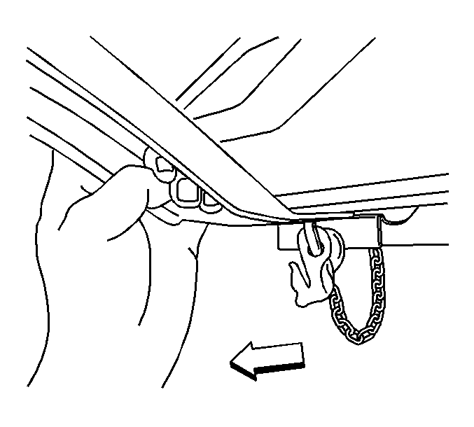
- Pull the right side transmission support down only enough to allow installation of the chassis fuel hose/pipes.
 Courtesy of GENERAL MOTORS COMPANY
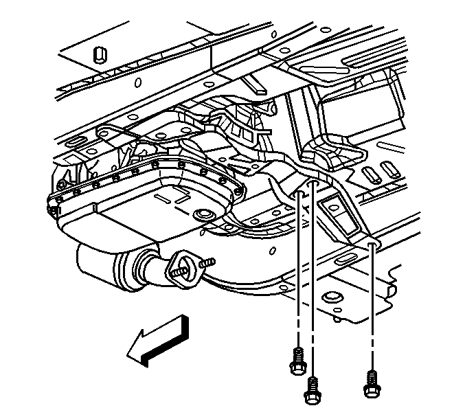
- Install the transmission support right side bolts. Refer to Transmission Support Replacement (Manual CTS-V)
, Transmission Support Replacement (Automatic CTS-V)
, Transmission Support Replacement (Automatic RWD except CTS-V)
, Transmission Support Replacement (Manual except CTS-V)
, Transmission Support Replacement (Automatic AWD)
.
 Courtesy of GENERAL MOTORS COMPANY
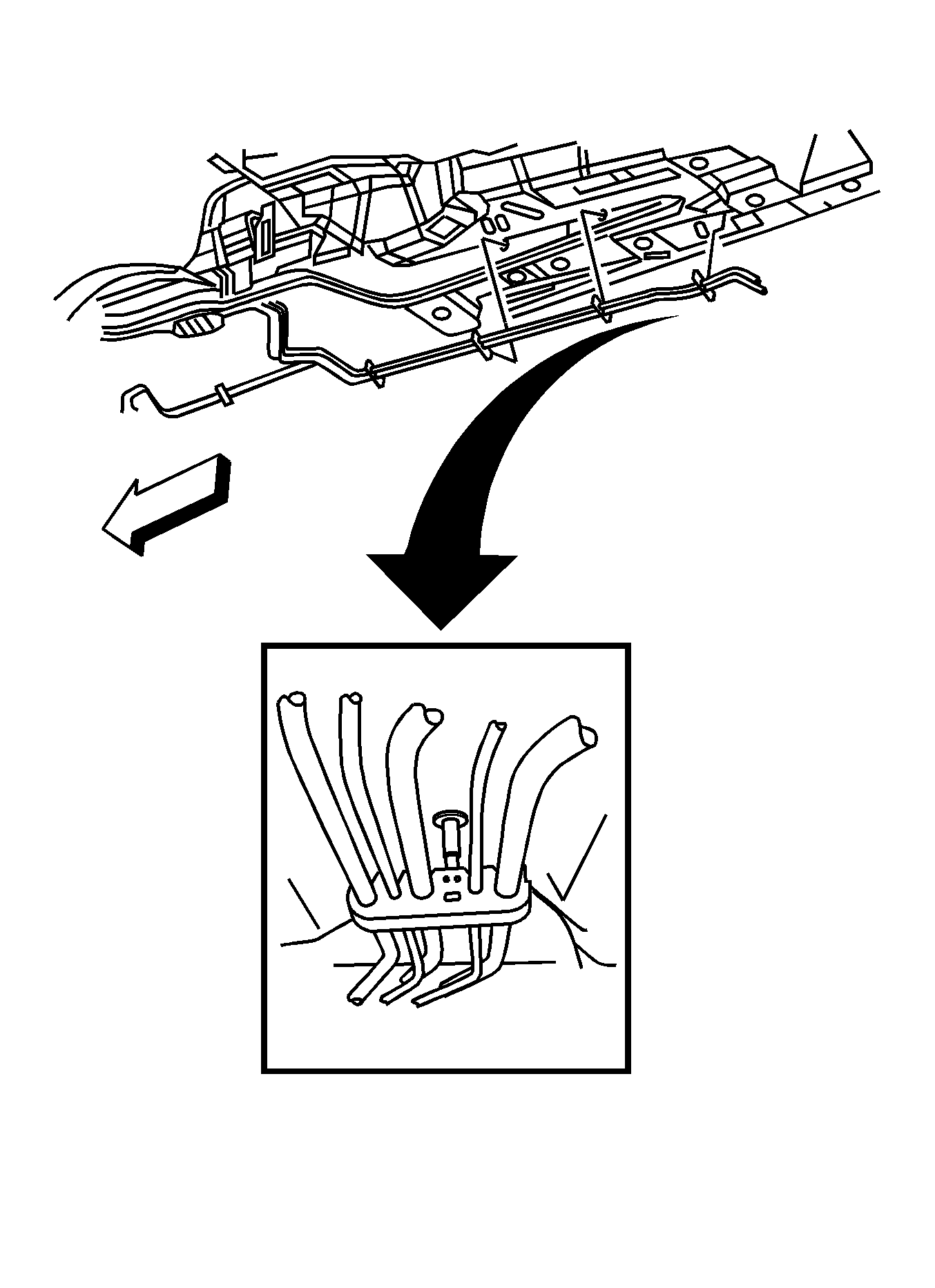
- Install the EVAP hose to the retainer.
- Install the fuel/brake bundle to the underbody.
 Courtesy of GENERAL MOTORS COMPANY
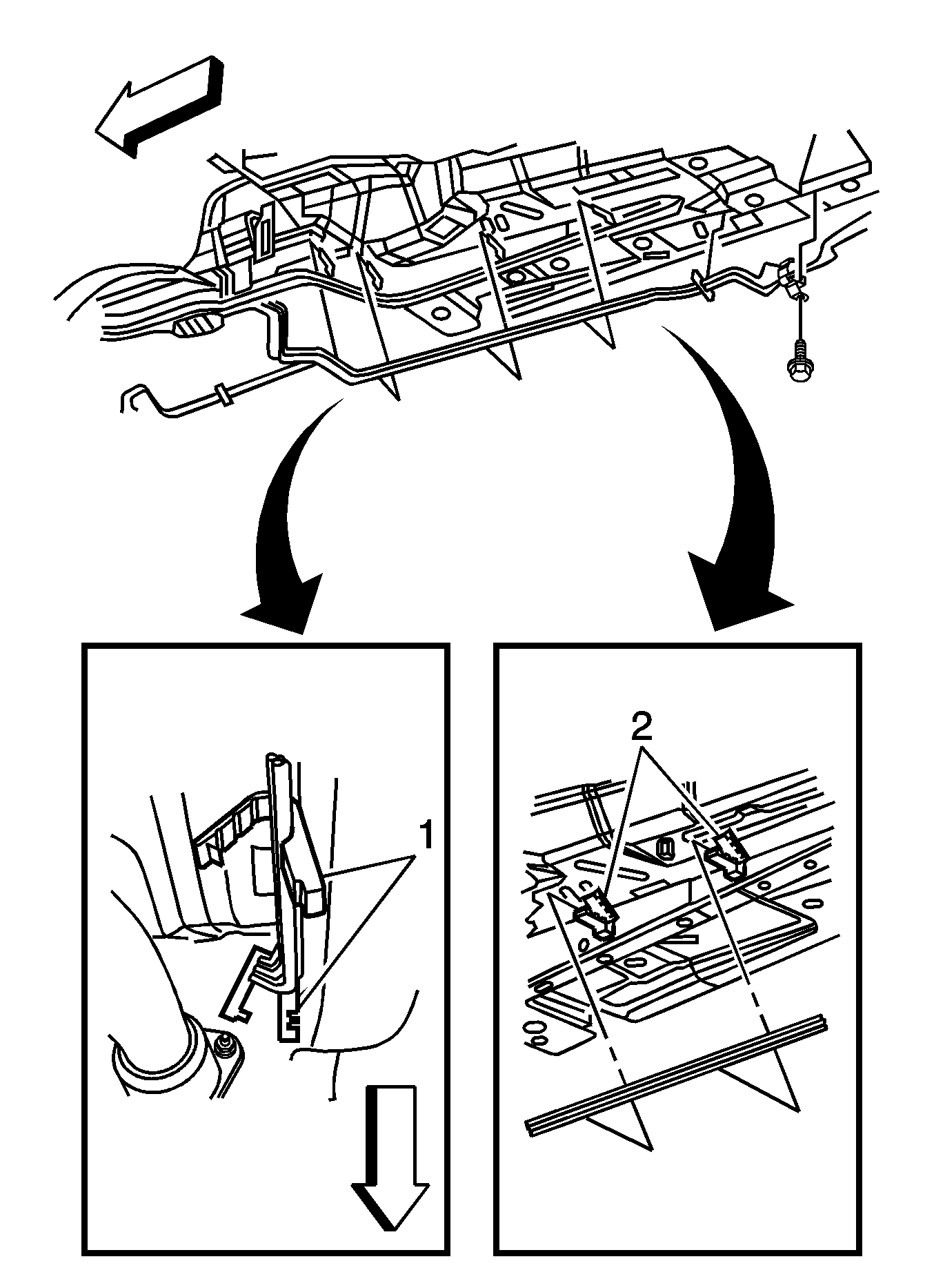
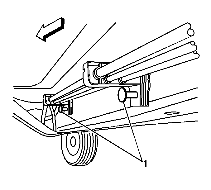
- Complete the following in order to install the chassis hose/pipes to the retainers (2) located at the rearward portion of the rail:
- Install the chassis hose/pipes into the retainers (2).
- Close the retainers (2) at the top.
- Insert the retainers (2) into the rail.
- Install the chassis hose/pipes into the retainers (1) located at the forward portion of the rail.
- Close the retainers.
 Courtesy of GENERAL MOTORS COMPANY
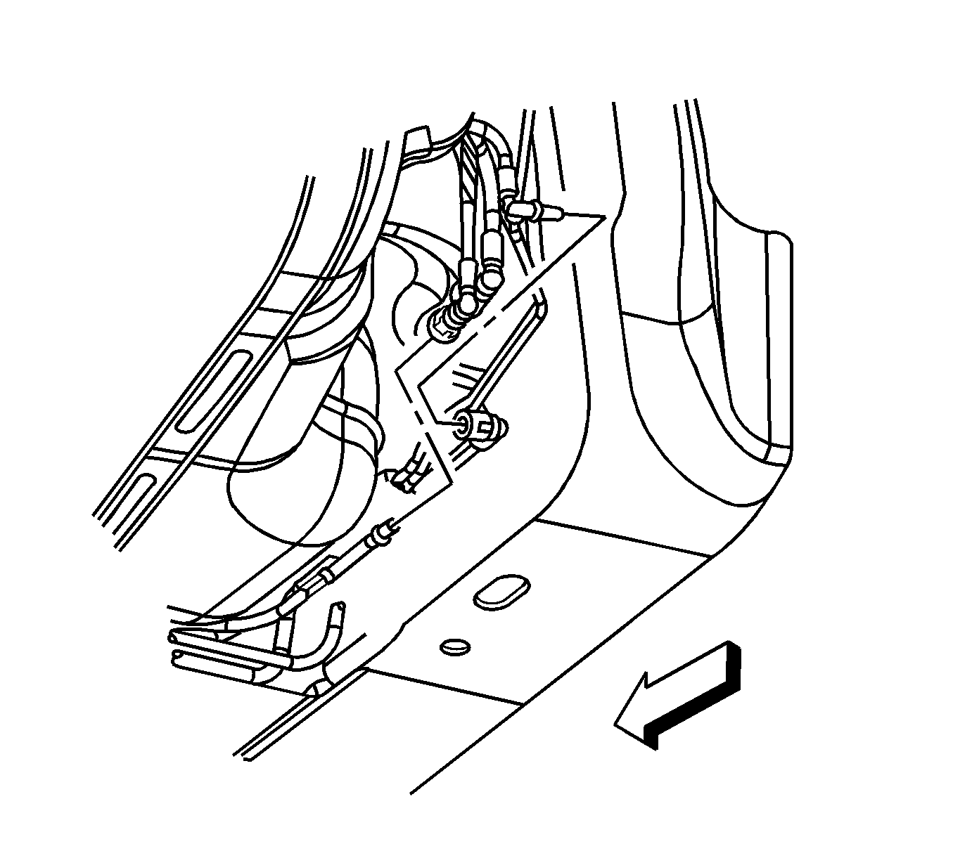
- Push the locking mechanism (1) inward in order to engage the fuel/brake bundle chassis pipe retainers to the rail.
 Courtesy of GENERAL MOTORS COMPANY
- Connect the fuel feed pipe and the EVAP hose to the fuel bundle.
- Lower the vehicle.
 Courtesy of GENERAL MOTORS COMPANY
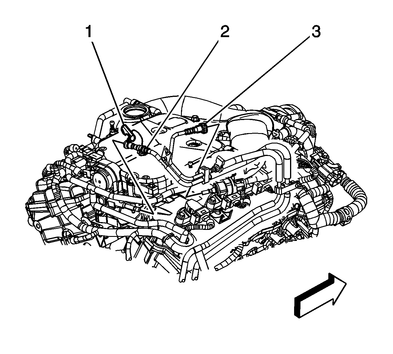
- Connect the evaporative emission (EVAP) purge line (3) to the purge solenoid.
- Connect the fuel feed pipe (1) to the fuel rail. Refer to Metal Collar Quick Connect Fitting Service
.
 Courtesy of GENERAL MOTORS COMPANY
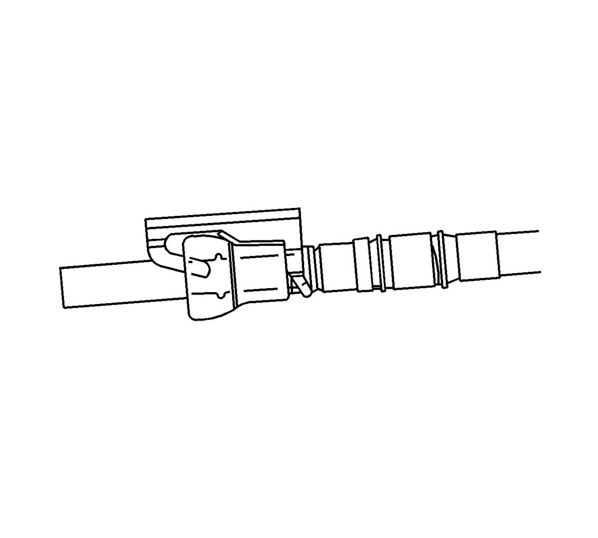
- Install the fuel pipe retaining clip.