Accessory DC Power Control Module Replacement
 Courtesy of GENERAL MOTORS COMPANY
 Accessory DC Power Control Module Replacement
| Callout |
Component Name |
WARNING:
Always perform the High Voltage Disabling procedure prior to servicing any High Voltage component or connection. Personal Protection Equipment (PPE) and proper procedures must be followed.
The High Voltage Disabling procedure includes the following steps:
- Identify how to disable high voltage.
- Identify how to test for the presence of high voltage.
- Identify condition under which high voltage is always present and personal protection equipment (PPE) and proper procedures must be followed.
Before working on any high voltage system, be sure to wear the following Personal Protection Equipment:
- Safety glasses with appropriate side shields when within 15 meters (50 feet) of the vehicle, either indoors or outdoors.
- Certified and up-to-date Class "0" Insulation gloves rated at 1000V with leather protectors.
- Visually and functionally inspect the gloves before use.
- Wear the Insulation gloves with leather protectors at all times when working with the high voltage battery assembly, whether the system is energized or not.
Failure to follow the procedures may result in serious injury or death.
Preliminary Procedures
- Disable the high voltage system. Refer to High Voltage Disabling
.
- Remove the accessory DC power control module cooling air inlet duct. Refer to Accessory DC Power Control Module Cooling Air Inlet Duct Replacement
.
- Remove the accessory DC power control module cooling air duct. Refer to Accessory DC Power Control Module Cooling Air Duct Replacement
.
- Disconnect the negative and positive cables from the accessory DC power control module. Refer to Battery Positive and Negative Cable Replacement (APM Module Ground Cable)
, Battery Positive and Negative Cable Replacement (B+ APM Module to Battery Fuse Block)
.
|
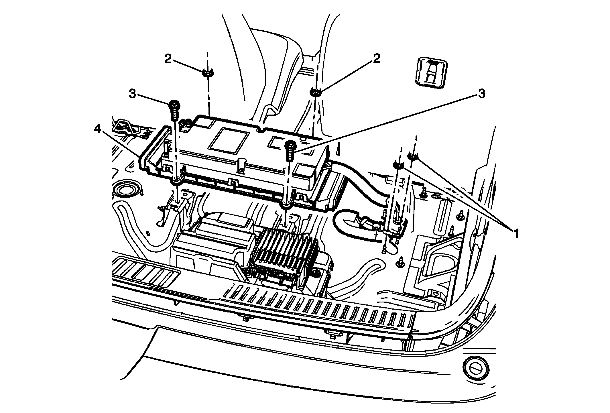
| 1 |
Battery Positive and Negative Cable Nut (Qty: 2)
Tighten
9 N.m (80 lb in) |
| 2 |
Accessory DC Power Control Module Nut (Qty: 2)
Tighten
22 N.m (16 lb ft) |
| 3 |
Accessory DC Power Control Module Bolt (Qty: 2)
Tighten
19 N.m (14 lb ft) |
| 4 |
Accessory DC Power Control Module Procedure
- Raise the vehicle to access the connector. Refer to Lifting and Jacking the Vehicle
.
- Disconnect the electrical connector underneath the vehicle.
|