DTC P1380-00; Electric Variable Valve Timing Control Circuit Problem: Notes
DTC DETECTION DESCRIPTION
| DTC P1380:00 |
Electric variable valve timing control circuit problem |
| DETECTION CONDITION |
- A malfunction is detected in the results of the on-board diagnostic test received from the electric variable valve timing driver.
Diagnostic support note
- This is a continuous monitor (CCM).
- The check engine light does not illuminate.
- FREEZE FRAME DATA is not available.
- Snapshot data is available.
- DTC is stored in the PCM memory.
|
| FAIL-SAFE FUNCTION |
- Stops activation of the electric variable valve timing driver.
|
| POSSIBLE CAUSE |
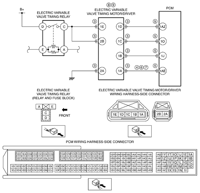
- Electric variable valve timing motor/driver connectors or terminals malfunction
- Short to ground in wiring harness between electric variable valve timing motor/driver terminal 1A and PCM terminal 1AE
- PCM connector or terminals malfunction
- Short to power supply in wiring harness between electric variable valve timing motor/driver terminal 1A and PCM terminal 1AE
- Open circuit in wiring harness between electric variable valve timing motor/driver terminal 1A and PCM terminal 1AE
- Electric variable valve timing driver malfunction
- Electric variable valve timing motor malfunction
- PCM malfunction
|
 Courtesy of MAZDA MOTORS CORP.
CAUTION:
- Verify the malfunction symptom according to not only the PID value but also the symptom troubleshooting.
PARTS DESCRIPTION
| Item |
Definition |
Unit |
Condition/Specification |
| VT_IN_ACT |
Actual intake variable valve timing control
- Advance amount from max retard position
|
° (deg) |
- Displays actual intake variable valve timing- advance amount from max retard position
|
| VT_IN_DES |
Target intake variable valve timing control
- Advance amount from max retard position
|
° (deg) |
- Displays target intake variable valve timing- advance amount from max retard position
|