Diagnosis & Repair Procedure
- Check for DTCs. See RETRIEVING DIAGNOSTIC TROUBLE CODES under SELF-DIAGNOSTIC SYSTEM. If DTC P0463 is set, test that DTC first. See DTC P0463: FUEL LEVEL SENSOR CIRCUIT, HIGH INPUT . If DTC P0463 is not set, go to next step.
- If not using scan tool, go to next step. If using scan tool, turn ignition off. Connect scan tool. Turn ignition on. Check fuel level on scan tool. Add one gallon (3.7L) of fuel to fuel tank. Recheck fuel level. If fuel level increases on scan tool, problem is intermittent. System is okay at this time. See TROUBLE SHOOTING - NO CODES article. If intermittent problem is not found, replace PCM and retest system. If fuel level does not increase, go to step 4.
- Turn ignition on. Backprobing, measure voltage between ground and PCM 35-pin connector E61 terminal No. 28 (Blue/White wire). See Figure. Note voltage reading. Turn ignition off. Add one gallon (3.7L) of fuel to fuel tank. Turn ignition on. Measure voltage between ground and PCM 35-pin connector E61 terminal No. 28 (Blue/White wire). If voltage is now lower, problem is intermittent. System is okay at this time. See TROUBLE SHOOTING - NO CODES article. If intermittent problem is not found, replace PCM and retest system. If voltage is not lower, go to next step.
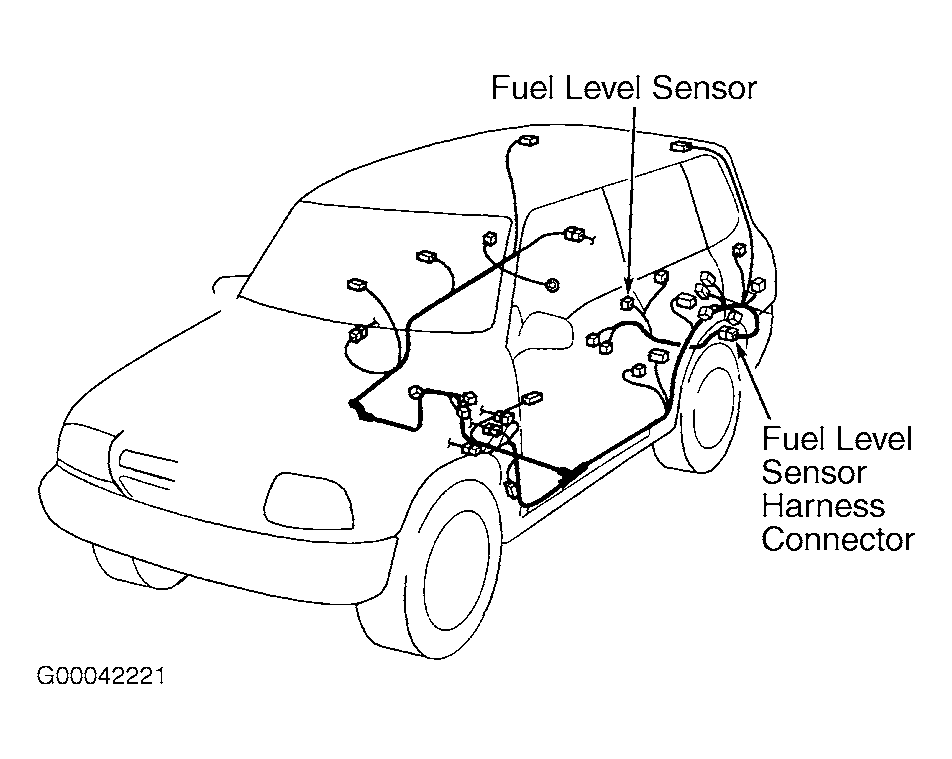
- Turn ignition off. Disconnect 12-pin fuel level sensor harness connector. See Fig 1. Check for poor terminal contact at fuel level sensor connector. If poor terminal contact is found, repair as necessary. If terminal contact is okay, measure resistance between component side of 12-pin fuel level sensor harness connector terminals No. 3 (Black/Yellow wire) and No. 4 (Blue/White wire) as one gallon (3.7 L) of fuel is added to fuel tank. See WIRING DIAGRAMS article. Go to next step.
- If resistance decreases smoothly within a 2-130 ohm range, go to next step. If resistance does not decrease, or resistance is out of range, check for short or open in Blue/White wire between fuel level sensor, fuel level gauge and PCM 35-pin connector E61 terminal No. 28. See WIRING DIAGRAMS article. Also check for short or open in Black/Yellow wire between fuel level sensor and ground. If wires are okay, replace fuel level sensor and retest system.
- Disconnect PCM 35-pin connector E61. Check for good terminal contact at PCM 35-pin connector E61. If poor terminal contact is found, repair as necessary. If terminal contact is okay, turn ignition on. With fuel level sensor disconnected, fuel level gauge should indicate empty. Connect a fused jumper wire between ground and harness side of 12-pin fuel level sensor harness connector terminals No. 4 (Blue/White wire). Go to next step.
- Fuel level gauge should indicate full. If fuel level gauge operates as specified, replace PCM and retest system. If fuel level gauge does not operate as specified, check for short or open in Blue/White wire between fuel level sensor, fuel level gauge and PCM 35-pin connector E61. See WIRING DIAGRAMS article. If wire is okay, replace fuel level gauge and retest system.
 Courtesy of SUZUKI OF AMERICA CORP.