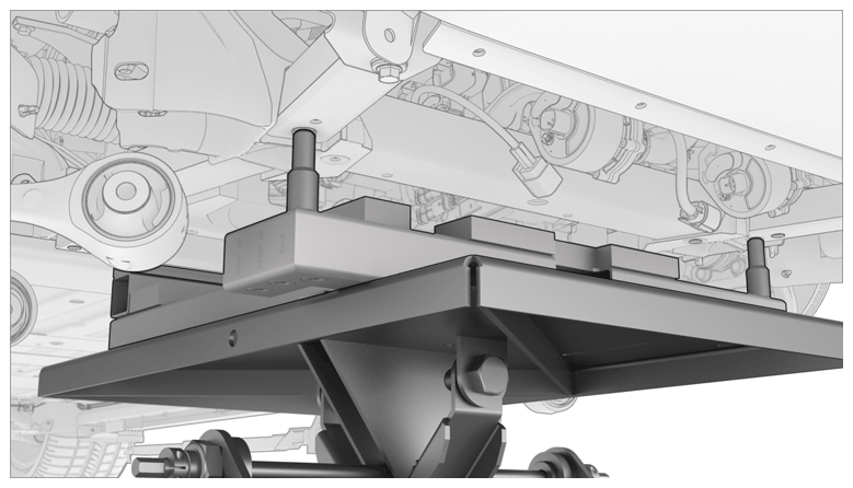
- Position the front drive unit assembly under the vehicle for installation.
- Use the transmission jack and the MS/X drive unit cradle to raise the front drive unit assembly into the vehicle.
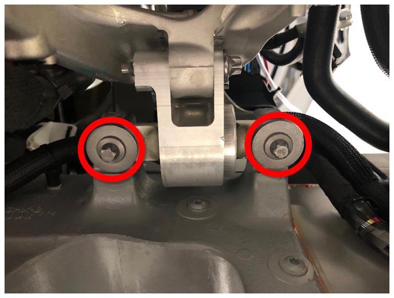
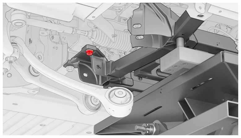
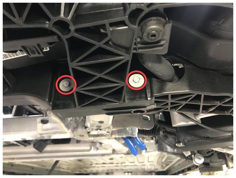
- Hand-tighten the bolts (x2) that attach the LH front drive unit mount to the body.
NOTE:
The LH front drive unit mount bolts will be tightened to specifications later in this procedure (torque 65 N.m).
 Courtesy of TESLA, INC. Courtesy of TESLA, INC.
|
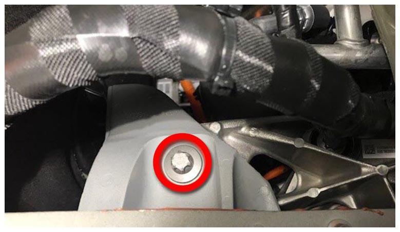
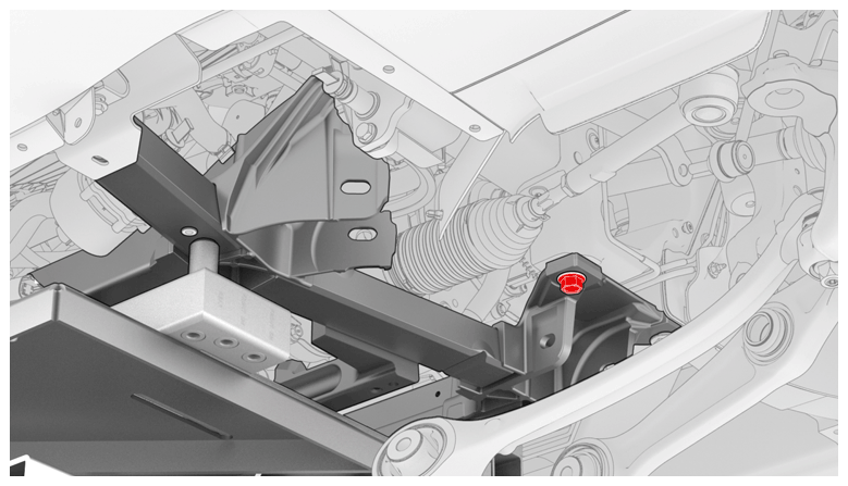
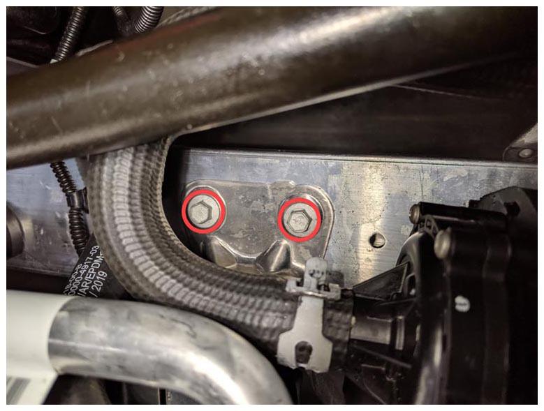
- Raise the front drive unit until the RH mount bolt holes are aligned, and then hand-tighten the bolt.
NOTE:
The RH front drive unit mount bolt will be tightened to specifications later in this procedure (torque 120 N.m).
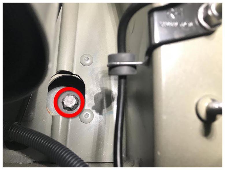
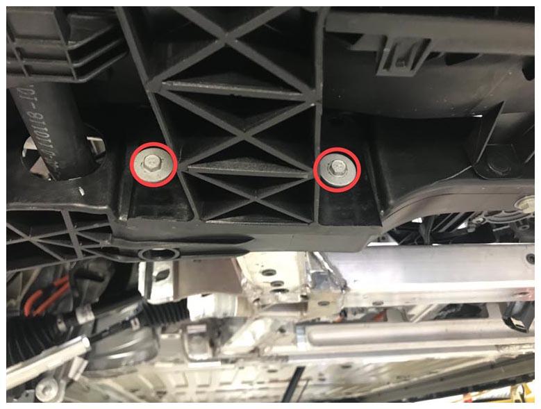
- Install the bolts (x2) that attach the RH front drive unit mount to the body (torque 120 N.m).
 Courtesy of TESLA, INC. Courtesy of TESLA, INC.
|
 Courtesy of TESLA, INC. Courtesy of TESLA, INC.
|
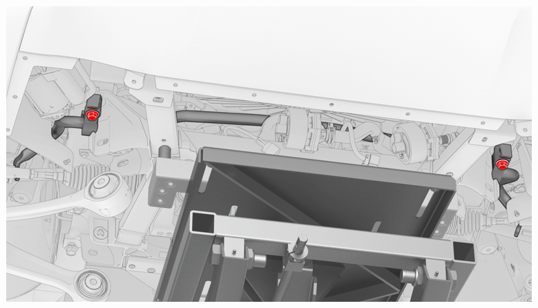
- Tighten the bolts (x2) that attach the LH front drive unit mount to the body (torque 65 N.m).
 Courtesy of TESLA, INC. Courtesy of TESLA, INC.
|
- Lower the front drive unit stand and the underhoist stand away from the front drive unit assembly.
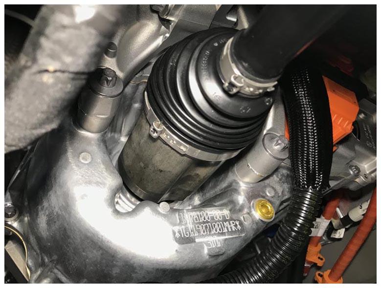
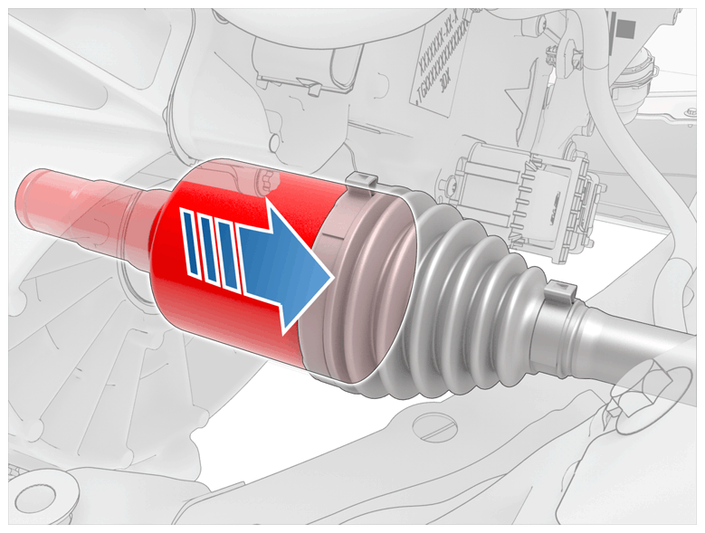
- Install the LH halfshaft into the front drive unit assembly.
CAUTION:
Make sure that the halfshaft is fully seated into the front drive unit. An audible click is heard when the C-clip is fully engaged.
CAUTION:
Do not damage or displace the oil seal.
 Courtesy of TESLA, INC. Courtesy of TESLA, INC.
|
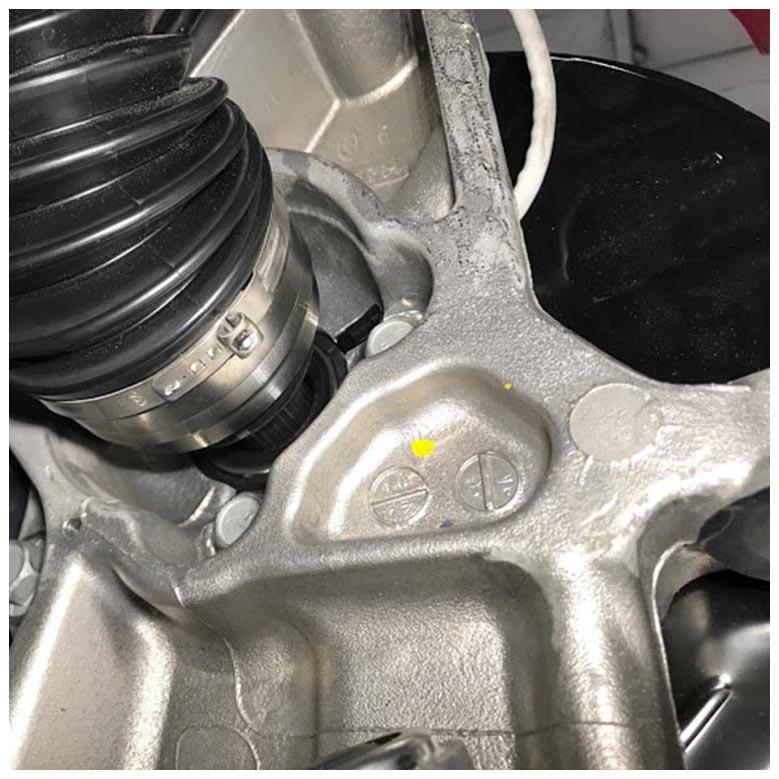
- Apply no more than 1 gram of Molykote M-77 lubricant paste only to the hub mating face on the outboard side of the halfshaft.
CAUTION:
Do not apply any lubricant to the halfshaft splines. If lubricant is mistakenly applied, wipe the splines clean with a shop towel.
 Courtesy of TESLA, INC. Courtesy of TESLA, INC.
|
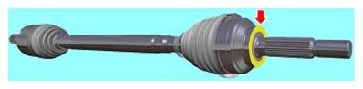
- Verify that the halfshaft is fully seated:
- Carefully push the halfshaft into the drive unit until there is an audible "click" from the halfshaft stub contacting the pinion shaft.
- There will be a slight pulling sensation on the halfshaft as the halfshaft circlip locks into place.
- Pull on the inner halfshaft cup to confirm that the circlip is locked into place. If the halfshaft detaches from the drive unit then reinstall the halfshaft and then test that it is fully seated.
 Courtesy of TESLA, INC. Courtesy of TESLA, INC.
|
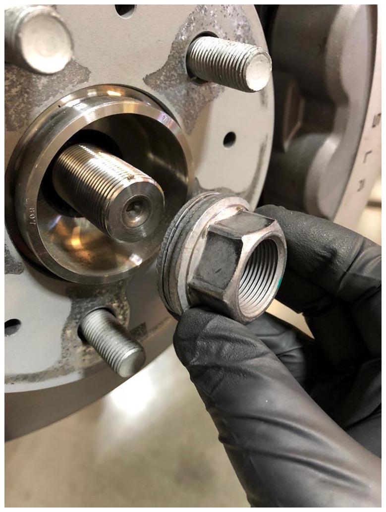
- Install the LH halfshaft into the hub, and then hand-tighten the nut and a new washer.
NOTE:
The nut can be reused.
NOTE:
Tightening of the nut will be done a later step.
 Courtesy of TESLA, INC. Courtesy of TESLA, INC.
|
 Courtesy of TESLA, INC. Courtesy of TESLA, INC.
|
- Repeat steps 9 - 12 on the RH halfshaft.
- Put the front subframe assembly with the powertrain table under the vehicle for installation.
- Raise the front subframe assembly into position to be installed.
CAUTION:
Do not work on the front subframe assembly while it is under the vehicle.
CAUTION:
Do not damage the front end carrier while the front subframe assembly is raised to the vehicle. The powertrain table must be tilted on the rear side angle down, and the front side tilted up as the front subframe is clearing the front end carrier.
 Courtesy of TESLA, INC. Courtesy of TESLA, INC.
|
- Install the RH rear bolt that attaches the front subframe assembly to the body (torque 115 N.m). Repeat this step on the LH rear bolt.
 Courtesy of TESLA, INC. Courtesy of TESLA, INC.
|
 Courtesy of TESLA, INC. Courtesy of TESLA, INC.
|
- Install the bolt that attaches the RH stabilizer bar mount to the body through the front subframe assembly (torque 80 N.m). Repeat this step on the LH stabilizer bar mount.
 Courtesy of TESLA, INC. Courtesy of TESLA, INC.
|
- Install new bolts (x4) that attach the bumper carrier to the front subframe assembly (torque 7.5 N.m).
 Courtesy of TESLA, INC. Courtesy of TESLA, INC.
|
 Courtesy of TESLA, INC. Courtesy of TESLA, INC.
|
- Lower the powertrain table, and then remove it from under the vehicle.
- Disconnect the shop air supply from the powertrain table.
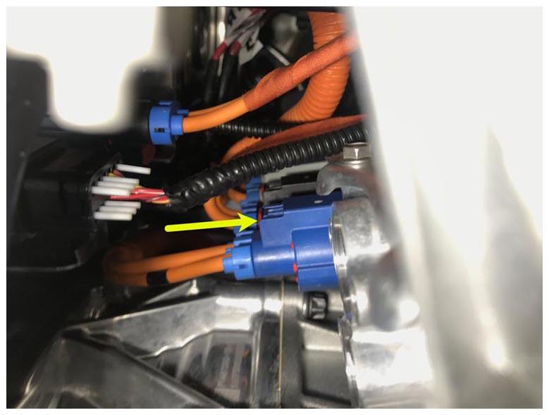
- Connect the A/C HV cable to the FJB.
 Courtesy of TESLA, INC. Courtesy of TESLA, INC.
|
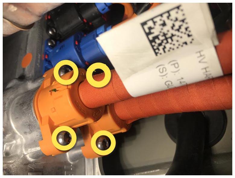
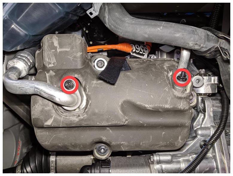
- Install new bolts (x4) that attach the Front Junction Box (FJB)-to-front drive unit HV harness to the FJB.
 Courtesy of TESLA, INC. Courtesy of TESLA, INC.
|
- Put the coolant drain container under the LH front corner of the vehicle to catch any coolant during the next step.
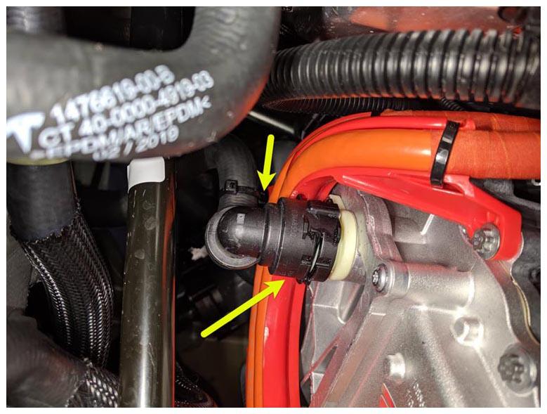
- Remove the hose plugs, and then connect the front drive unit inlet hose.
 Courtesy of TESLA, INC. Courtesy of TESLA, INC.
|
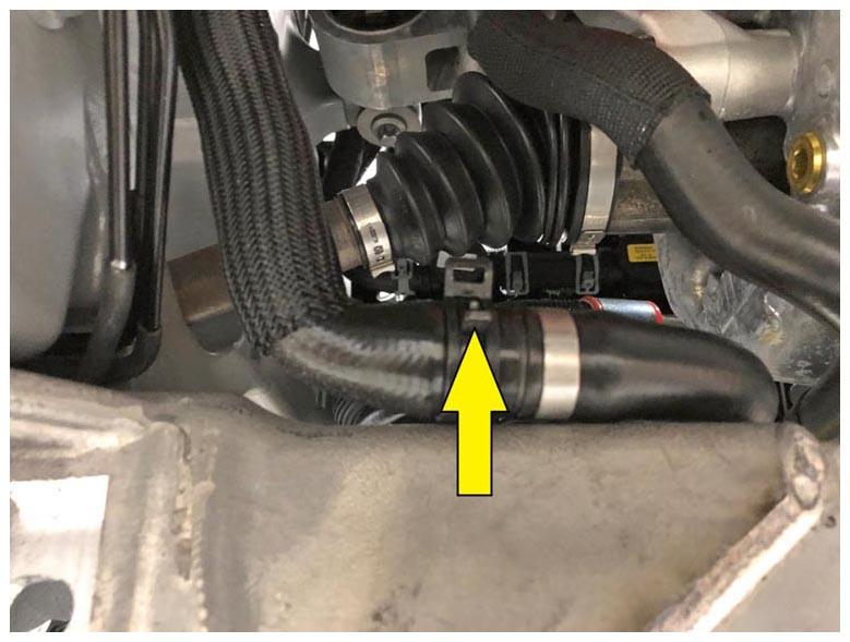
- Remove the hose plugs, and then install the battery coolant heater-to-coolant pump 2 hose at the rear of the front subframe assembly and secure it with the hose clamp.
 Courtesy of TESLA, INC. Courtesy of TESLA, INC.
|
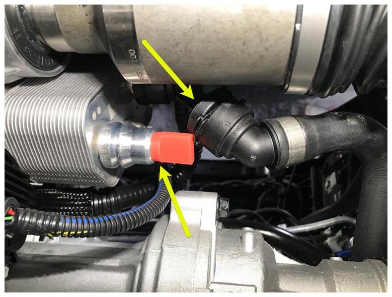
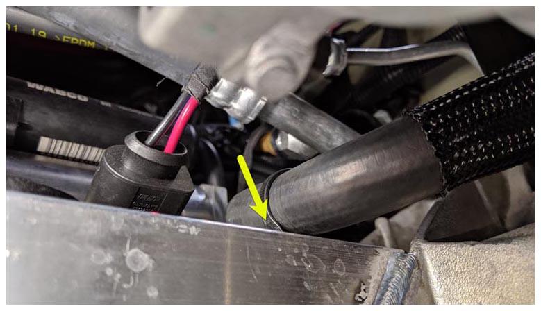
- Remove the hose plug, and then secure the hose clip and the fir tree clip that attach the coolant hose to the radiator inlet.
 Courtesy of TESLA, INC. Courtesy of TESLA, INC.
|
 Courtesy of TESLA, INC. Courtesy of TESLA, INC.
|
- Remove the coolant drain container from under the vehicle.
- Slide the lower i-shaft onto the steering rack, and then install the bolt that attaches the lower i-shaft to the steering rack (torque 30 N.m).
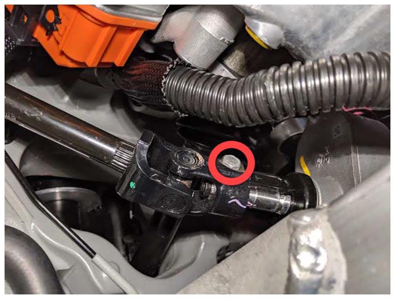 Courtesy of TESLA, INC. Courtesy of TESLA, INC.
|
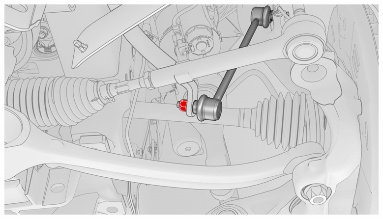
- Install a new nut that attaches the RH stabilizer bar to the stabilizer bar end link (torque 70 N.m). Repeat this step on the LH stabilizer bar.
NOTE:
LH shown, RH similar
 Courtesy of TESLA, INC. Courtesy of TESLA, INC.
|
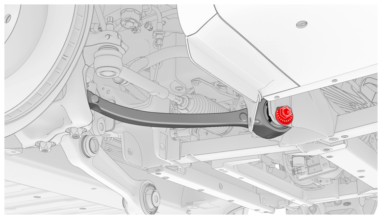
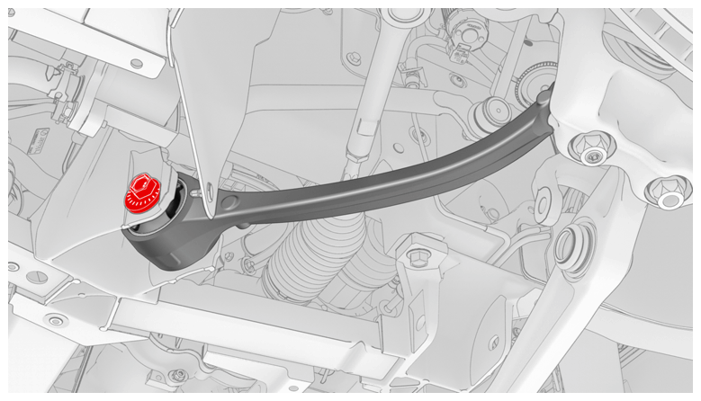
- Move the RH front fore link into the front subframe assembly, properly align the paint marks, and then hand-tighten the bolt that attaches the RH front lower fore link to the subframe.
NOTE:
The bolt will be fully tightened during wheel alignment later in this procedure (torque specification for the bolt is 130 N.m).
 Courtesy of TESLA, INC. Courtesy of TESLA, INC.
|
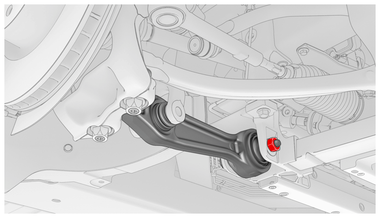
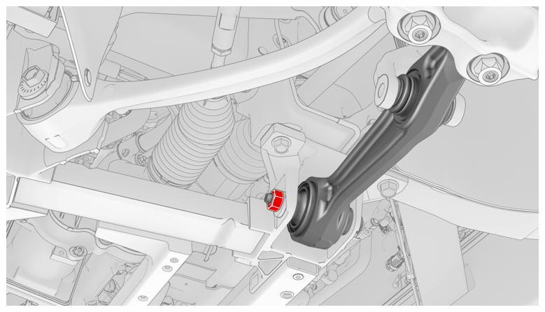
- Move the RH front lower aft link into position on the front subframe assembly, and then hand-tighten the bolt.
NOTE:
Make sure that the bolt is installed with the bolt head facing the front of the vehicle.
NOTE:
The bolt will be fully tightened during wheel alignment later in this procedure (torque specification for the bolt is 130 N.m).
 Courtesy of TESLA, INC. Courtesy of TESLA, INC.
|
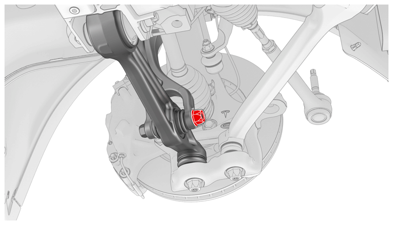
- Move the LH front lower fore link into the front subframe assembly, properly align the paint marks, and then hand-tighten the bolt that attaches the link to the subframe.
NOTE:
The bolt will be fully tightened during wheel alignment later in this procedure (torque specification for the bolt is 130 N.m).
 Courtesy of TESLA, INC. Courtesy of TESLA, INC.
|
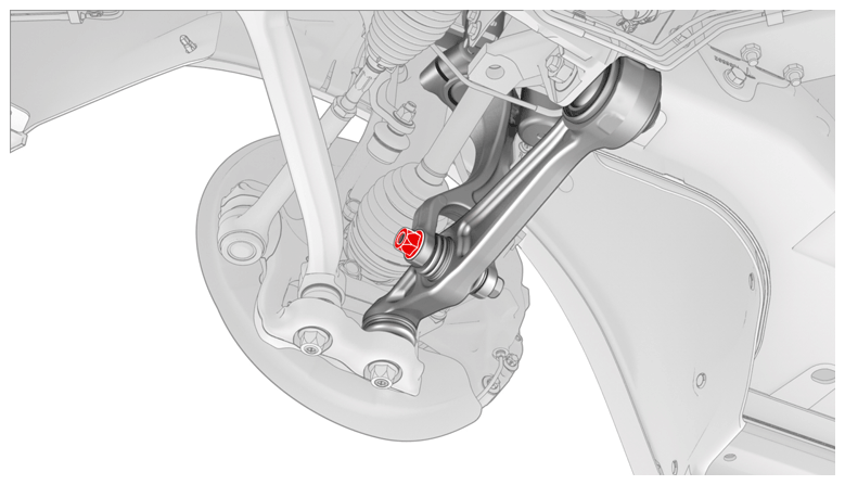
- Move the LH front lower aft link into position on the front subframe assembly, and then hand-tighten the bolt that attaches the link to the subframe.
NOTE:
Make sure that the bolt is installed with the bolt head facing the front of the vehicle.
NOTE:
The bolt will be fully tightened during wheel alignment later in this procedure (torque specification for the bolt is 130 N.m).
 Courtesy of TESLA, INC. Courtesy of TESLA, INC.
|
- Install the bolt that attaches the LH front strut to the front lower aft link. Repeat this step on the RH front strut.
NOTE:
Torque the bolts at ride height when the vehicle is on the alignment rack later in this procedure (torque specification for the bolt is 140 N.m).
NOTE:
LH side
 Courtesy of TESLA, INC. Courtesy of TESLA, INC.
|
NOTE:
RH side
 Courtesy of TESLA, INC. Courtesy of TESLA, INC.
|
- Install the front subframe skid bar. See Skid Bar - Front Subframe (Remove and Replace)
.
- Install the front skidplate. See Skidplate - Front (Remove and Replace)
.
- Install the front bash plate stamping. See Bash Plate - Front - Stamping (Remove and Replace)
.
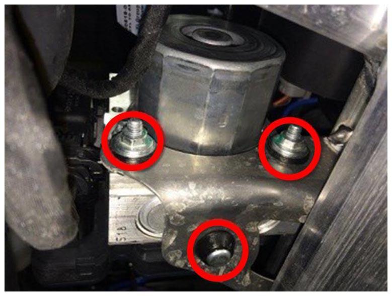
- Install the ABS pump onto the rubber mounting grommet, and then install the nuts (x2) that attach the ABS pump to the front subframe (torque 9 N.m).
 Courtesy of TESLA, INC. Courtesy of TESLA, INC.
|
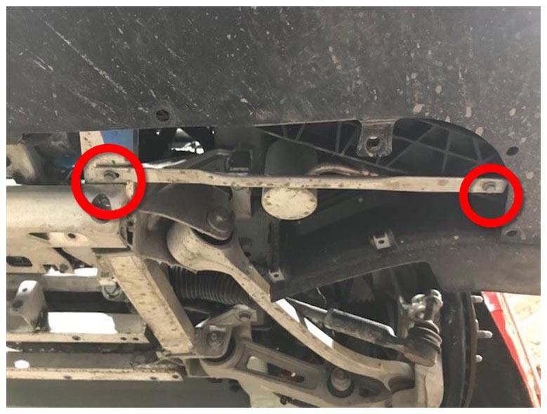
- Install the bolts (x2) that attach the LH stay bar to the front subframe assembly (torque 11 N.m). Repeat this step on the RH stay bar.
 Courtesy of TESLA, INC. Courtesy of TESLA, INC.
|
- Install the front aero shield panel. See Panel - Aero Shield - Front (Remove and Replace)
.
- Install the HV battery assembly. See HV Battery (RWD/AWD) (Remove and Install)
.
- Install the front extrusion bash plate. See Bash Plate - Front - Extrusion (Remove and Replace)
.
- Install the mid aero shield panel. See Panel - Aero Shield - Mid (Remove and Replace)
.
- Lower the vehicle partially.
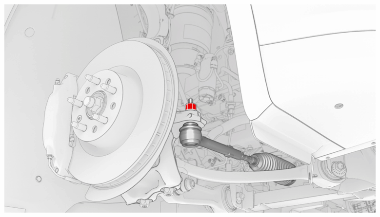
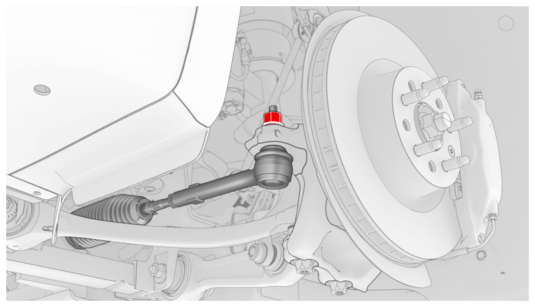
- Install the LH tie rod end into the knuckle, and then install a new LH nyloc nut that attaches the tie rod end to the steering knuckle (torque 103 N.m). Repeat this step on the RH tie rod end.
 Courtesy of TESLA, INC. Courtesy of TESLA, INC.
|
 Courtesy of TESLA, INC. Courtesy of TESLA, INC.
|
- Install the LH and RH front wheels. See Wheel (Remove and Install)
.
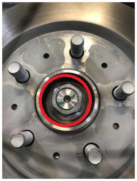
NOTE:
Before installing the LH and RH front wheel center caps, tighten the LH and RH front axle nuts (torque 245 N.m).
 Courtesy of TESLA, INC. Courtesy of TESLA, INC.
|
- Install the RH front wheel arch liner. See Wheel Arch Liner - Front - LH (Remove and Replace)
.
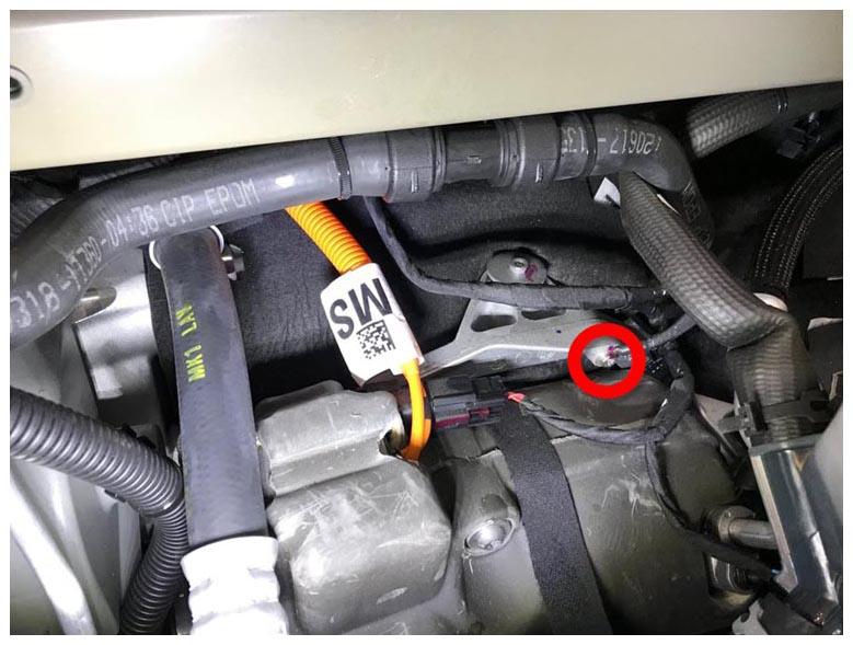
- Install the bolt that attaches the ground connector at the A/C compressor mounting bracket (torque 7 N.m).
 Courtesy of TESLA, INC. Courtesy of TESLA, INC.
|
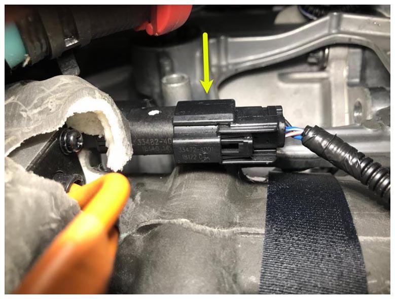
- Connect the A/C compressor logic electrical connector.
 Courtesy of TESLA, INC. Courtesy of TESLA, INC.
|
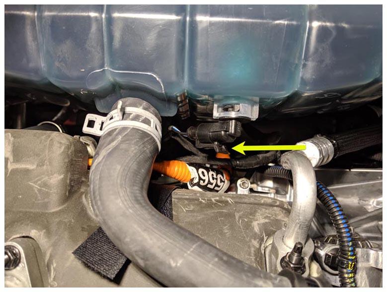
- Connect the coolant reservoir level sensor electrical connector.
 Courtesy of TESLA, INC. Courtesy of TESLA, INC.
|
- Install new O-rings, and then install the nuts (x2) that attach the A/C lines to the compressor (torque 10 N.m).
 Courtesy of TESLA, INC. Courtesy of TESLA, INC.
|
- Install the clip that secures the front drive unit logic connector harness.
 Courtesy of TESLA, INC. Courtesy of TESLA, INC.
|
- Connect the logic connector at the front drive unit assembly.
 Courtesy of TESLA, INC. Courtesy of TESLA, INC.
|
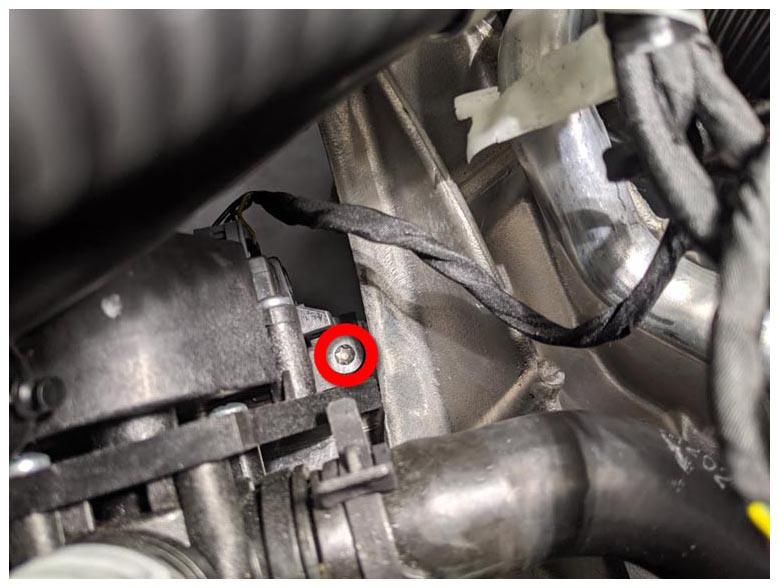
- Install the bolt that attaches the ground strap to the front drive unit assembly (torque 6 N.m).
 Courtesy of TESLA, INC. Courtesy of TESLA, INC.
|
- Install the 12V battery bracket beam. See 12V Battery Bracket Beam (Remove and Replace)
.
- Install the 12V auxiliary battery, but do not connect the negative battery terminal at this time. See Battery - Auxiliary - 12V (Remove and Replace)
.
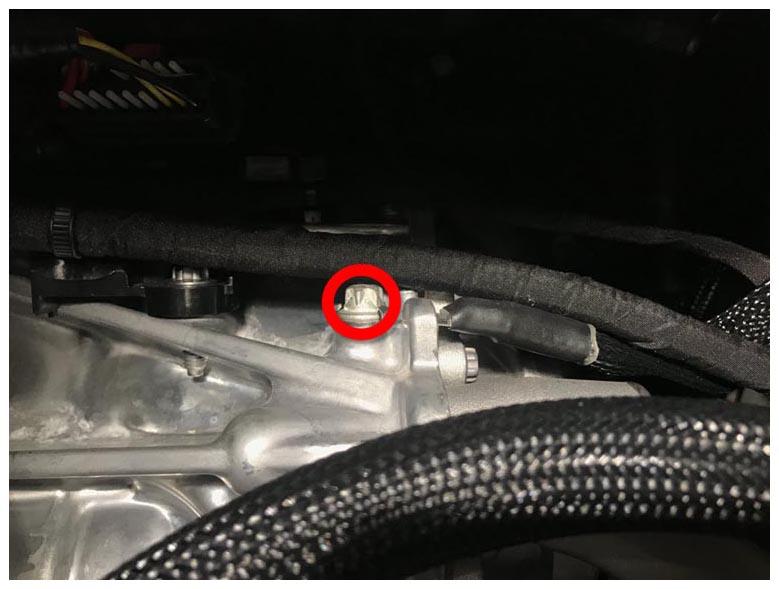
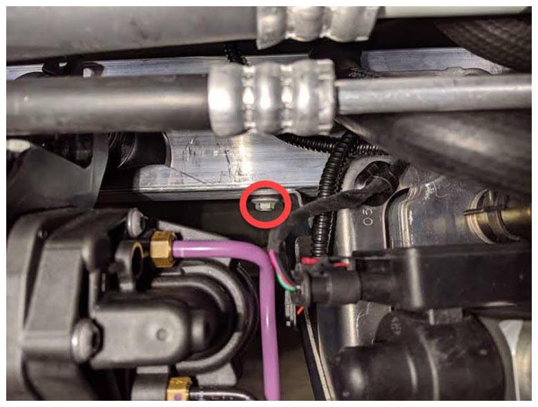
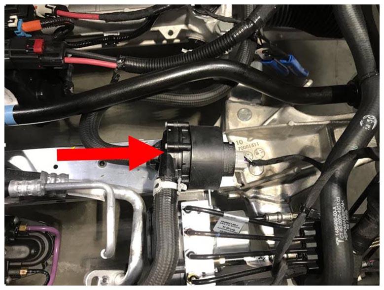
- Install the RH bolt that attaches the 3-way valve to the front subframe assembly.
 Courtesy of TESLA, INC. Courtesy of TESLA, INC.
|
- Release the bungee cords that attach the air suspension pump bracket and the chiller assembly to the front end carrier.
 Courtesy of TESLA, INC. Courtesy of TESLA, INC.
|
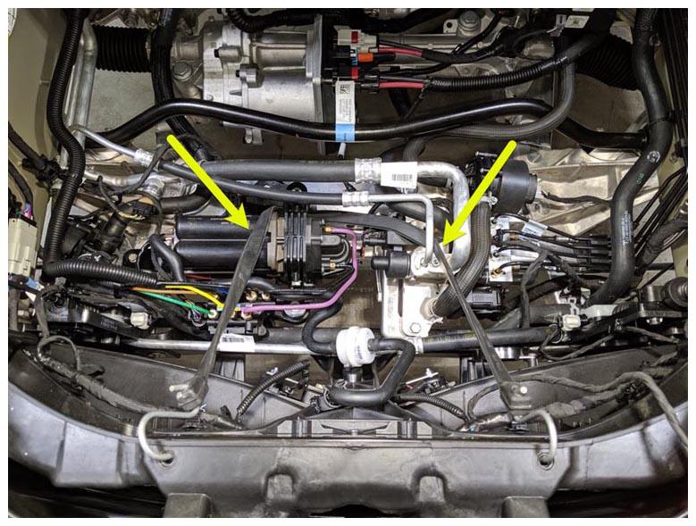
- Install the bolts (x2) that attach the air suspension pump bracket to the front subframe assembly (torque 5.5 N.m).
 Courtesy of TESLA, INC. Courtesy of TESLA, INC.
|
- Install the bolts (x3) that attach the chiller assembly to the front subframe assembly (torque 5 N.m).
 Courtesy of TESLA, INC. Courtesy of TESLA, INC.
|
 Courtesy of TESLA, INC. Courtesy of TESLA, INC.
|
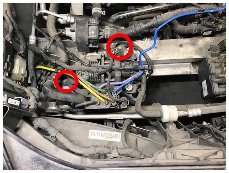
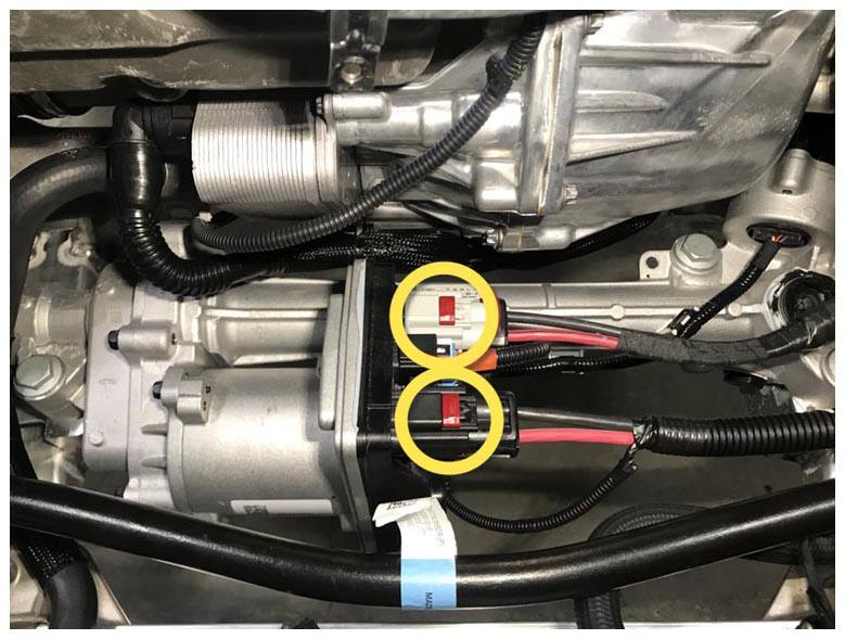
- Connect the electrical connectors (x2) for the logic for the steering rack.
 Courtesy of TESLA, INC. Courtesy of TESLA, INC.
|
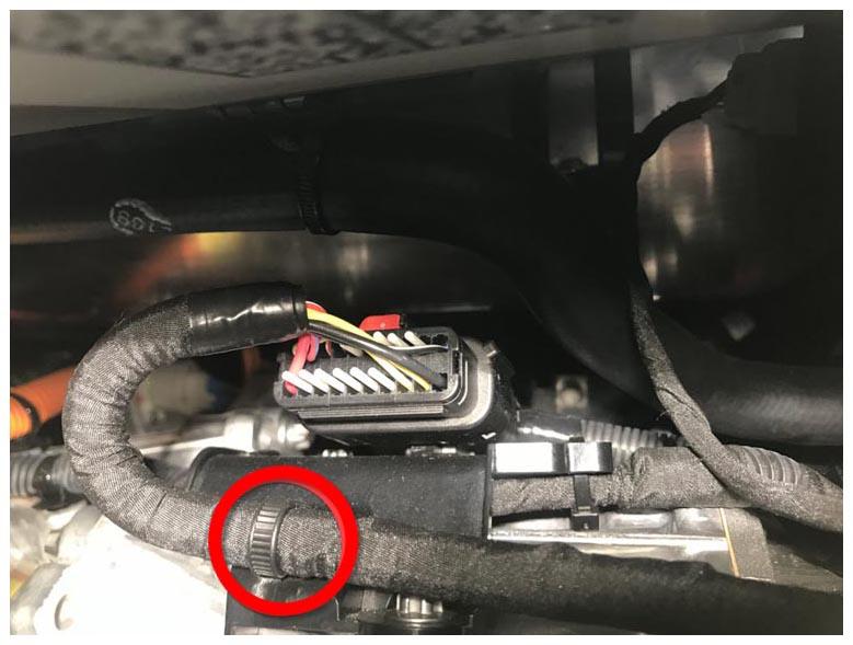
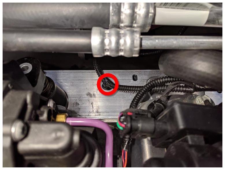
- Install the fir tree clip that attaches the logic harness connector to the front subframe assembly.
 Courtesy of TESLA, INC. Courtesy of TESLA, INC.
|
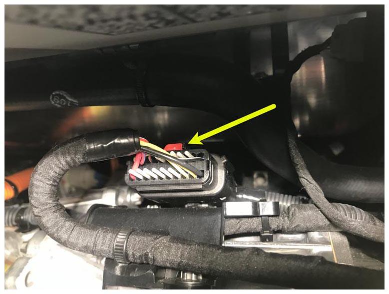
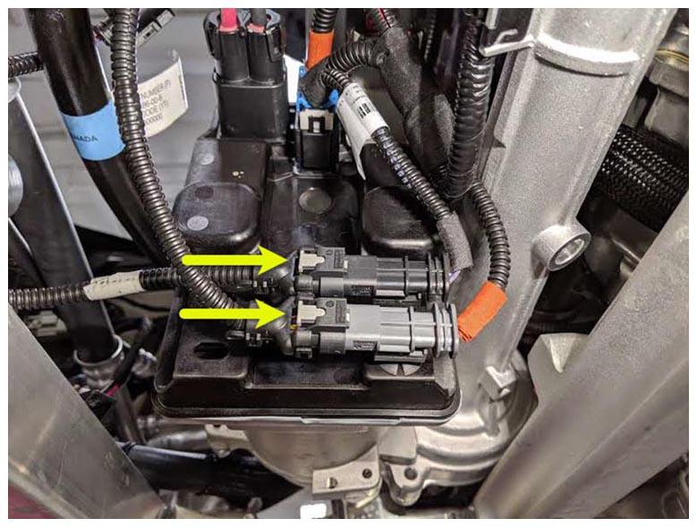
- Connect the steering rack electrical connectors (x2).
NOTE:
The electrical connectors feature 2-stage locking: Make sure that the locking tab is engaged after an audible click is heard when each steering rack electrical connector is connected.
 Courtesy of TESLA, INC. Courtesy of TESLA, INC.
|
- Slide the battery pump 2 into the mounting bracket that is attached to the front subframe assembly.
 Courtesy of TESLA, INC. Courtesy of TESLA, INC.
|
- Connect the First Responder Loop and the 12V battery negative terminal (torque 5 N.m).
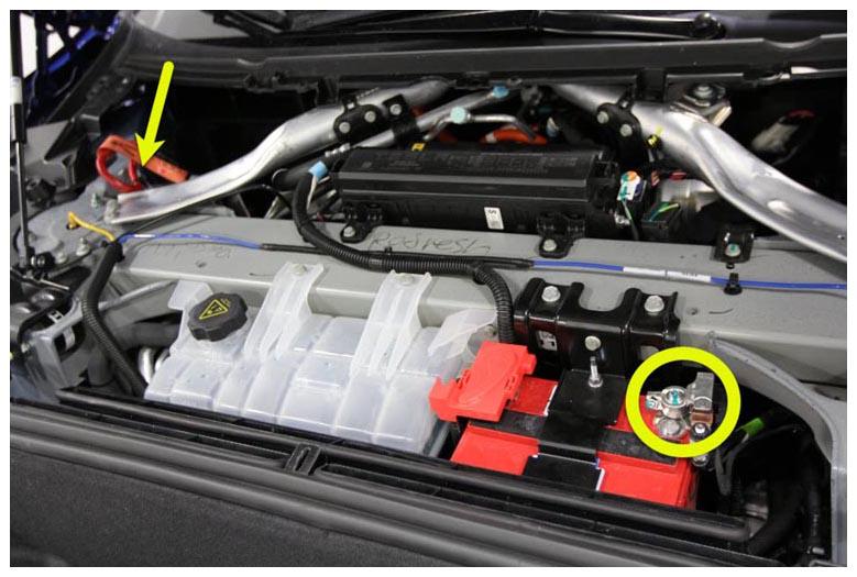 Courtesy of TESLA, INC. Courtesy of TESLA, INC.
|
- Recharge the A/C refrigerant. See A/C Refrigerant Recovery and Recharge (Remove and Replace)
.
NOTE:
Continue this procedure until the A/C refrigerant recharge is complete.
- Install the underhood storage unit. See Underhood Storage Unit (Remove and Install)
.
- Install the underhood storage carpet. See Carpet - Underhood Storage (Remove and Install)
.
- Install the front underhood apron. See Underhood Apron - Front (Remove and Replace)
.
- Install the HEPA filter outlet duct. See Duct - HEPA Filter - Outlet (Remove and Replace)
.
- Disconnect the A/C refrigerant high side and the low side hoses from the vehicle, and then install the dust caps on the service ports.
- Install the HEPA filter inlet duct. See Duct - HEPA Filter - Inlet (Remove and Replace)
.
- Install the LH and RH underhood aprons. See Underhood Apron - LH (Remove and Replace)
.
- Test the climate control in the vehicle to make sure that it functions as designed.
- Connect a laptop with Toolbox to the vehicle.
- In Toolbox, click Panels
> Thermal
> Coolant Air Purge
.
- Use Toolbox to perform a firmware update.
- Remove the steering wheel holder from the vehicle.
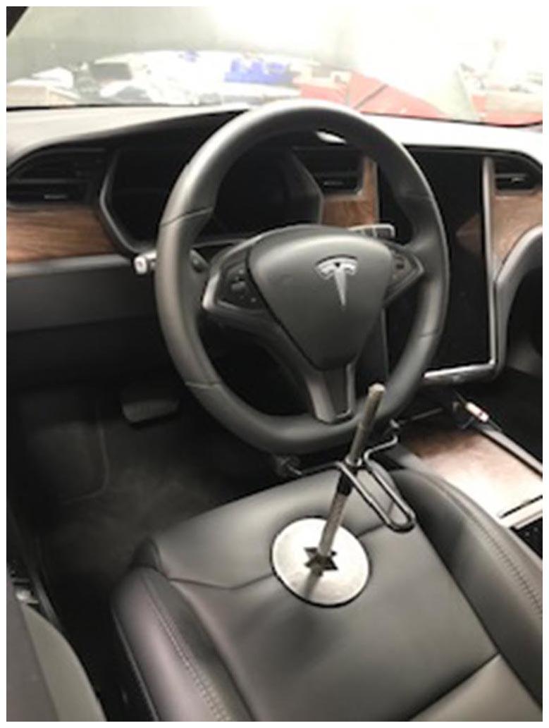 Courtesy of TESLA, INC. Courtesy of TESLA, INC.
|
- Restore the front passenger seat back to its original position.
- Install the rear center underhood apron. See Underhood Apron - Rear (Remove and Replace)
.
- Close the hood.
- Remove the vehicle from the 2-post lift.
- Perform a four wheel alignment. See Four Wheel Alignment Check (Coil Suspension)
or Four Wheel Alignment Check (Air Suspension)
.
- Install the mid aero shield. See Panel - Aero Shield - Mid (Remove and Replace)
.
- Perform a test drive.