Removal
POWER DISTRIBUTION: MAIN BODY ECU: REMOVAL
1. REMOVE LOWER NO. 1 INSTRUMENT PANEL AIR BAG ASSEMBLY
Removal
2. REMOVE INSTRUMENT PANEL JUNCTION BLOCK ASSEMBLY
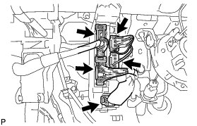
(a) Disconnect the 5 connectors.
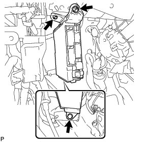
(b) Remove the bolt and 2 nuts, and disconnect the instrument panel junction block assembly.
(c) Disengage the claw and disconnect the connector as shown in the illustration.
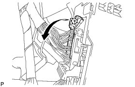
(d) Disengage the claw and release the connector lock as shown in the illustration.
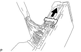
(e) Disengage the claw and disconnect the connector as shown in the illustration to remove the instrument panel junction block assembly.
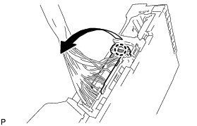
3. REMOVE MAIN BODY ECU (MULTIPLEX NETWORK BODY ECU)
(a) Press the claw of the junction block as shown in the illustration to release the lock.
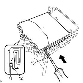
Text in Illustration
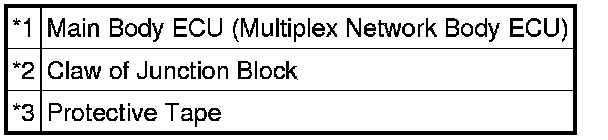
(b) With the junction block lock released, insert a screwdriver with its tip wrapped with protective tape horizontally between the main body ECU (multiplex network body ECU) and junction block.
NOTICE:
Use a screwdriver with a diameter of between 5.0 mm (0.197 in.) and 6.3 mm (0.248 in.) and a length of approximately 90 mm (3.54 in.).
(c) Using the screwdriver, carefully raise the main body ECU (multiplex network body ECU) up to the position where the connector becomes disengaged.
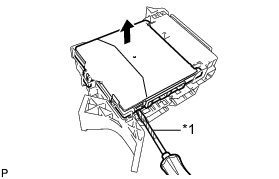
Text in Illustration

NOTICE:
Do not insert the screwdriver opening between the junction block and the connector of the main body ECU (multiplex network body ECU).
Do not twist the screwdriver to raise the main body ECU (multiplex network body ECU).
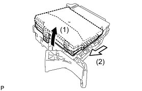
(d) Raise the main body ECU (multiplex network body ECU) as shown by the arrow (1), and then pull it out as shown by the arrow (2) in the illustration.
NOTICE:
Do not touch the ECU connector.